|
| |
TM 5-5-4120-287-15
(b) Clean the area to be repainted.
(c) Paint the area with zinc chromate primer, MIL Spec MIL-P-6889A, type I.
(d) After the primer dries, paint with one coat of semi-gloss olive drab per MIL Spec MIL-T-704, Type A. Color
to be in accordance with Federal Specification TT-E-485C, Type II, Color Number X24087.
3-23. Evaporator Left-side Access Panel Assembly
a.
Removal. Remove the eighteen phillips head screws (8, fig. 3-7) securing the panel assembly (5) to the cabinet;
then remove the panel assembly from the air conditioner frame.
b.
Inspection, Cleaning, Repair and Replacement. Perform the applicable procedures of paragraph 3-22.
c.
Installation. Secure the panel assembly (5) to the air conditioner frame with the phillips head screws (8).
3-24. Evaporator Blower Access Panel Assembly
a.
Removal. Remove the eighteen phillips head screws (4, fig. 3-7) securing the panel assembly (1) to the cabinet;
then remove the panel assembly from the air conditioner frame.
b.
Inspection, Cleaning, Repair and Replacement. Perform the applicable procedures of paragraph 3-22.
c.
Installation. Secure the panel (1) to the air conditioner frame with the phillips head screws (4).
3-25. Electrical Tray Access Panel Assembly
a.
Removal. Remove the twelve phillips head screws (11, fig. 3-7) securing the panel assembly (9) to the cabinet; then
remove the panel assembly from the air conditioner frame.
b.
Inspection, Cleaning, Repair and Replacement. Perform the applicable procedures of paragraph 3-22.
c.
Installation. Secure the panel assembly (5) to the air conditioner frame with the phillips head screws (11).
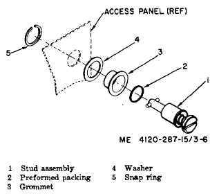
Figure 3-6. Quarter-turn fastener assembly
3-26. Thermostat Access Panel
a.
Removal
(1) Remove the electrical tray access panel according to paragraph 3-25a.
(2) Remove the seven phillips head screws (13, fig. 3-7) securing the thermostat access panel (12) to the
cabinet; then remove the thermostat access panel from the air conditioner frame.
b.
Inspection, Cleaning, Repair and Replacement. Perform the applicable procedures of paragraph 3-22.
c.
Installation. Secure the panel (12) to the air conditioner frame, using the phillips head bolts (13).
3-27. Evaporator Rear Access Panel
a.
Removal. Loosen the panel’s twenty quarter-turn fasteners by depressing fasteners and rotating one-quarter turn
counterclockwise; then remove the panel assembly (7, fig. 3-8) from the air conditioner frame.
b.
Inspection, Cleaning, Repair and Replacement. Perform the applicable procedures of paragraph 3-22.
c.
Installation. Secure the panel (7, fig. 3-8) to the air conditioner frame with the quarter-turn fasteners.
3-12
|