 |
|||
|
|
|||
|
Page Title:
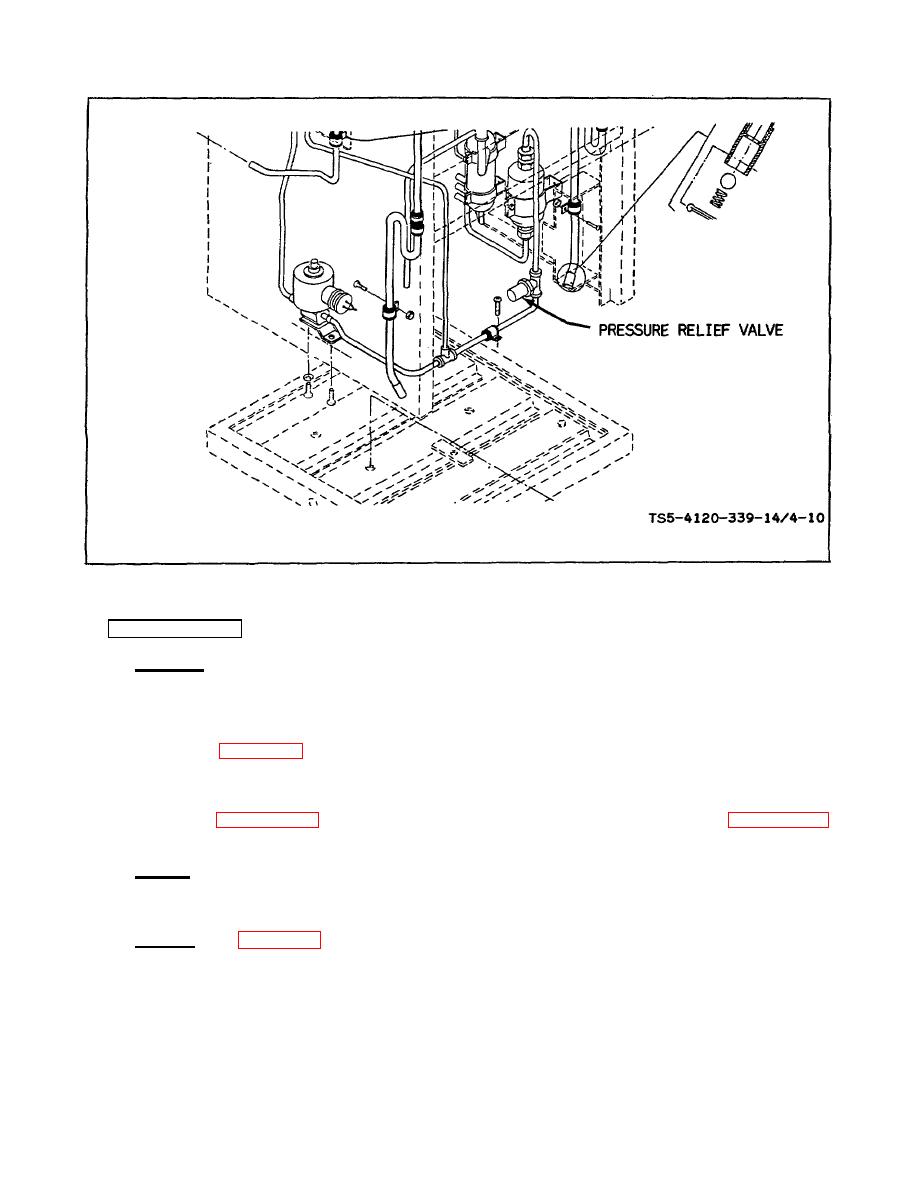
Figure 4-10. Location of pressure relief valve |
|
||
| ||||||||||
|
|
 TM 5-4120-339-14
Figure 4-10. Location of pressure relief valve
4-14.
SERVICE VALVES.
a. Inspection.
(1) Turn the selector switch to the "OFF" position and disconnect the air conditioner from the electrical power
source.
(2) Refer to figure 4-11 and inspect the suction pressure service valve and the discharge pressure service
valve externally for obvious defects. Make sure that the valve caps are tightly in place, that the valve stems are tightly
closed, and that the cap nuts are seated securely on the valves.
(3) Refer to paragraph 4-4c and check the service valves for refrigerant leaks. Refer to paragraph 4-4d and
repair any leaks found.
b. Replace. If damage or defects are found which could impair serviceability, replace the suction service valve
and/or the discharge pressure service valve. Refer to paragraphs c and d for removal of defective valve or valves and the
installation of new valves.
c.
Removal. (See figure 4-11.)
NOTE
Do not remove service valves unless one or both valves are to be replaced.
4-24
|
|
Privacy Statement - Press Release - Copyright Information. - Contact Us |
|
|
Integrated Publishing, Inc. - A (SDVOSB) Service Disabled Veteran Owned Small Business
|

