|
| |
TM5-4120-375-14
COMPRESSOR (CONT.)
LOCATION/ITEM
ACTION
REMARKS
- - - - - - - - - - - - - - - - - - - - - - - - - - - - - - - - - - - - - - - - - - - - - - - - - - - - - - - - - - - - - - - - - - - - - - - - - - - -
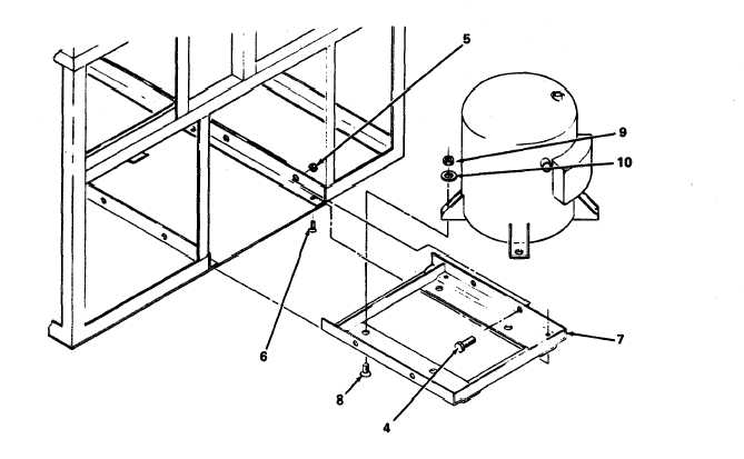
INSTALLATION
10. Compressor
a .
b .
c .
d.
e .
f .
g .
h.
i .
Align compressor (3) with holes in compressor
tray (7).
Secure compressor to compressor tray with four
bolts (8), nuts (9) and shoulder washers (10).
Slide compressor and compressor tray into unit.
Align compressor tray with holes in frame.
Secure compressor tray with four bolts (4) and
nuts (5), and four counter-sunk screws (6) to
frame.
Braze compressor in accordance with paragraph
5-15.
Leak check, evacuate and charge system in
accordance with paragraphs 5-16 thru 5-18.
Re-glue rubber insulation around suction line.
Connect electrical connector (P-1) to compressor.
5-91
|