|
| |
TM 9-4120-367-14
TM 07592B-14/1
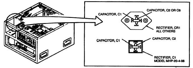
Figure 5-1. Capacitor C1
Location/Item
Action
Remarks
Installation
a. Slip heat-shrink tubing over capacitor leads and
Figures FO-1, FO-3, FO-5,
leads X36A20N and V6D20 (CR1-2<>TB2-12 and
FO-7, or FO-9.
K5-9<>CR1-4 on model MHP-20-4-08).
b. Join one capacitor lead and wire V6D20
Attached to “+” terminal on
(CR1-2<>TB2-12 on model MHP-20-4-08).
MHP-20-4-08.
c. Join capacitor Iead and wire X36A20N
Attached to “-” terminal on
(K5-9<>CR1-4 on model MHP-20-4-08).
MHP-20-4-08.
d. Solder "quick disconnect” terminals to the wires.
e. Heat shrink tubing over the solder joint.
Use hot air dryer.
f. Push terminals onto rectifier CR1, terminals 2 and
Wire V6D20
4.
(CR1-2<>TB2-12) to terminal
2; X36A20N (K5-9<>CR1-4) to
terminal 4.
g. Attach remaining two wires to either of two AC ter-
minals.
h. Replace junction box.
i.
Replace top cover.
j. Connect power supply.
5-8
5.3 EMI CAPACITORS C2 AND C1. - Continued
|