|
| |
ARMY TM 9-4120-381-14
NAVY EE-000-CA-MMA-010/7053-AC
AIR FORCE TO 35E9-136-31
2-2.
OPERATOR'S CONTROLS AND INDICATORS Continued.
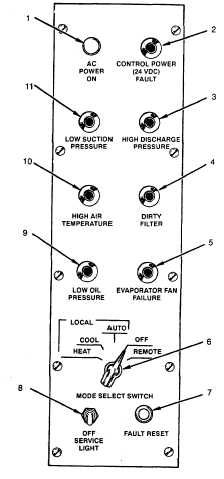
AC POWER ON (1) (green). Indicates ac input power on.
CONTROL POWER (24 VDC) FAULT (2) (red). Indicates dc power supply failure.
HIGH DISCHARGE PRESSURE (3) (red). Indicates excessive refrigerant pressure in compressor discharge line.
DIRTY FILTER (4) (red). Indicates dirty return air filter.
EVAPORATOR FAN FAILURE (5) (red). Indicates loss of air flow in supply air duct.
MODE SELECT Rotary SWITCH (6). Allows operation of air conditioner in LOCAL (HEAT, COOL and AUTO) or
REMOTE modes.
FAULT RESET Push Button (7). Used to reset fault indication circuits after repair.
SERVICE LIGHT Toggle Switch (8). Operates lamp in compressor compartment. Used for illumination during servicing.
LOW OIL PRESSURE (9) (red). Indicates loss of oil pressure in compressor crankcase.
HIGH AIR TEMPERATURE (10) (red). Indicates excessive air temperature at electric heater.
LOW SUCTION PRESSURE (11) (red). Indicates excessive low pressure in compressor suction line.
Figure 2-1. Controls and Indicators (Sheet 2 of 2)
2-2
|