 |
|||
|
|
|||
|
Page Title:
Installation of Slide Kit, Exhaust Kit, and Supplemental Kit - continued |
|
||
| ||||||||||
|
|
 MWO 55-8115-202-40-1
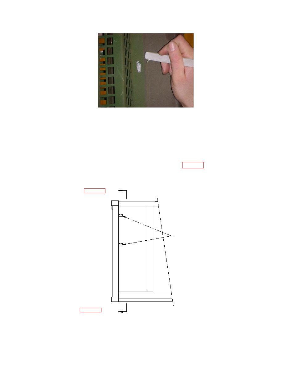
Figure 5C
(8) Drill and tap marked holes for guard using a size #22 (0.157" diameter) drill bit and a #10-24
UNC tap.
(8A) As an alternate, a 5/32" diameter rivet with a 1/4" grip range may be used in place of the
screws, and tapping is then not necessary. Rivets are not supplied with the kit.
(9) Weld two (2) brackets (Item 3.6, P/N 30694) to upright corner post on ladder side of container,
50 inches from inside bottom and 26 inches from bracket to bracket (Figure 6A, 6B, 6C, 6D and
6E). Mark the bracket locations and remove paint so that there is no paint within one inch
of the areas to be welded.
IN T E R IO R V IE W
BRACKET
30694
IN T E R IO R V IE W
Ladder Side of Container Exterior View
Figure 6A
14
|
|
Privacy Statement - Press Release - Copyright Information. - Contact Us |
