 |
|||
|
|
|||
|
|
|||
| ||||||||||
|
|
 MWO 55-8115-202-40-1
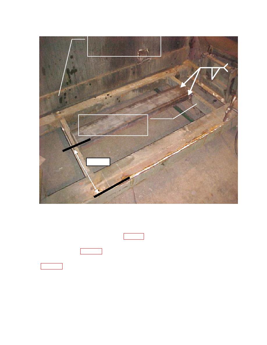
CROSSMEMBER A
X2
.25
CROSSMEMBER B
17.25''
Figure 7A
(10) Prepare the C-Channel (item 3.4) by grinding a chamfer (remove sharp edge) on the outside
edges of each end of the channel to create an approximately 1/8" chamfer. Locate the channel
between cross members A&B as shown on Figure 7A.
(11) Using a long straight bar (item 3.11), ensure that channel is level with front and rear
mounting structures (Figure 7B). Remove paint so that there is no paint within one inch of
the areas to be welded. Clamp and weld the 4-inch channel (opening of channel facing
downward) as shown with a 1/4" fillet weld, 17.25" from end of container to start of channel
four (4) holes left in the frame at which the original generator was mounted or cover the holes by
welding the four (4) 2" X 2" pieces of steel, Item 3.5, over the holes. Weld to create a watertight
covering.
17
|
|
Privacy Statement - Press Release - Copyright Information. - Contact Us |
