 |
|||
|
|
|||
|
Page Title:
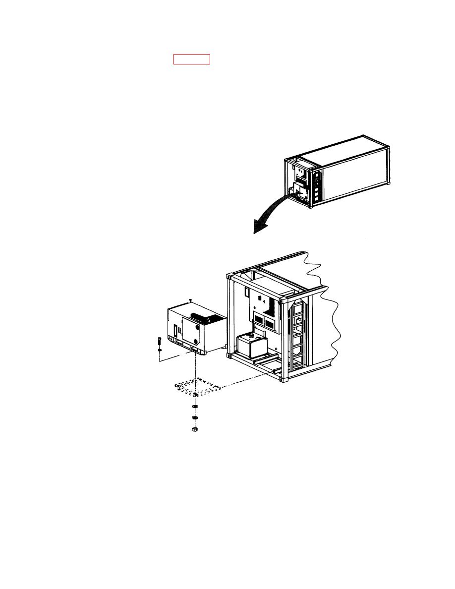
Figure 20. Generator Set Installation. |
|
||
| ||||||||||
|
|
 MWO 55-8115-202-40-1
(26) Install generator on mount (Figure 20). Be sure that the fuel tank end of the generator is on
ladder side of the container and control panel end of the generator is on the auxiliary fuel tank
Align mount holes in generator set with mounting holes in generator set slide. Secure at four
places with cap screw MS90725-113, hex nut MS51967-14, lock washer MS35338-48 and a flat
washer, MS27183-18 on each side of the generator mounting hole. Reference TM 55-8115-202-
14, Change 5, Paragraph 4-69, Figure 4-17.
Figure 20. Generator Set Installation.
32
|
|
Privacy Statement - Press Release - Copyright Information. - Contact Us |
