 |
|||
|
|
|||
|
Page Title:
AC HEATER CONTROL PANEL LIGHTS DO NOT OPERATE - continued |
|
||
| ||||||||||
|
|
 DRAFT
TB 9-2320-364-13&P-1
AC HEATER CONTROL PANEL LIGHTS DO NOT OPERATE - Continued
WARNING
Remove rings, bracelets, wristwatches, neck chains, and any other jewelry before working around
vehicle. Jewelry can catch on equipment and cause serious injury. Jewelry or tools may short
across electrical circuits or terminals and cause damage to equipment or severe burns or
electrical shock to personnel.
VISUAL INSPECTION
(1) Turn engine start switch OFF (TM 9-2320-364-10).
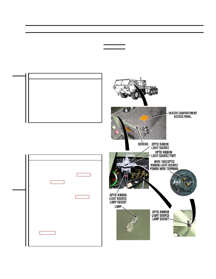
(2) Remove eight screws and heater compartment
access panel (TM 9-2320-364-20).
(3) Turn engine start switch ON (TM 9-2320-364-10).
NOTE: Optic ribbon light source operation is verified by
looking for light at the optic ribbon light source ports.
(4) Verify operation of optic ribbon light source.
(a) If optic ribbon light source does not illuminate,
go to Step 3 of this fault.
(b) If optic ribbon light source illuminates, go to
Step 5 of this fault.
VOLTAGE TEST
(1) Turn engine start switch OFF (TM 9-2320-364-10).
NOTE: Do not disconnect wire or optic ribbon from
optic ribbon light source in Step 2.
(2) Remove optic ribbon light source (WP 0042).
(3) Remove lamp socket and lamp from optic ribbon
light source (WP 0043).
CAUTION: Do not twist lamp while removing it from
lamp socket. Pull lamp straight out. Failure to comply
may cause damage to equipment.
(4) Remove lamp from lamp socket (WP 0043).
(5) Turn engine start switch ON (TM 9-2320-364-10).
(6) Place positive (+) probe of multimeter on cab
harness wire 1052/optic ribbon light source power
wire at optic ribbon light source lamp socket.
(7) Place negative (-) probe of multimeter on a known
good ground.
(a) If 12 to 14 vdc are not measured, turn engine
start switch OFF and repair cab harness wire
1052/optic ribbon light source power wire (see
go to Step 6 of this fault.
(b) If 22 to 28 vdc are measured, turn engine start
switch OFF, and go to Step 4 of this fault.
PLSAC219
|
|
Privacy Statement - Press Release - Copyright Information. - Contact Us |
