
TM 10-8145-222-23
0003
REFRIGERATION UNIT CONTINUED
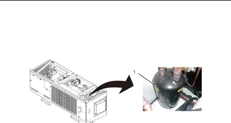
Accumulator. The accumulator (Figure 7, Item 1) is a refrigerant holding tank located in suction line between
evaporator and compressor. It prevents/minimizes liquid refrigerant (that may be in the suction line) from entering into
compressor resulting in internal damage. The compressor draws refrigerant vapor through outlet pipe of accumulator
which is equipped with an opening that controls oil return to compressor and prevents accumulation of oil within
accumulator tank.
Figure 7. Accumulator.