
TM 10-8145-222-23
0005
MAINTAINER MAINTENANCE REFRIGERATION UNIT TROUBLESHOOTING PROCEDURES
(FAULT CODES AL0 AL3, AL8) CONTINUED
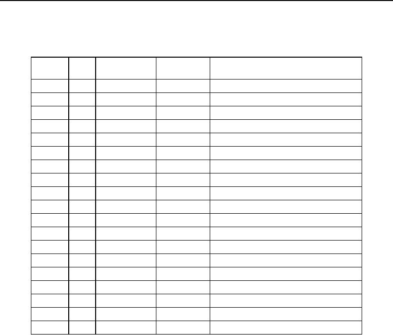
Table 1. Microprocessor Control Box Component Identification for Model MTRCS01 Continued.
MPC Box
Figure
Item
Component
Location
Nomenclature
1
28
Relay
Bottom
Capacitor Alternator Relay (CAR)
1
29
Buzzer
Bottom
Buzzer (B)
1
30
Capacitor
Bottom
C4
1
31
Capacitor
Bottom
C5
2
1
Relay
Forward Wall
Defrost Compartment Relay (DCR)
2
2
Detector
Forward Wall
Detector Power Supply (DPS)
2
3
Shunt
Door
Shunt (SH)
2
4
Relay
Door
Flash Relay (FLR)
2
5
Switch
Door
Run-stop Switch (RS)
2
6
Junction Block
Door
Junction Block
2
7
Relay
Door
Electric Heat Relay (Compartment 1)
2
8
Relay
Door
Electric Heat Relay (Compartment 2)
2
9
Relay
Door
Unloader Front Relay (UFR1)
2
10
Relay
Door
Unloader Front Relay (UFR2)
2
11
Board
Door
Microprocessor Board (MPC)
2
12
Connector
Door
P1 L-Y Connector
2
13
Connector
Door
P1 A-K Connector
3
1
Resistor
Aft Wall
Resistor (R)
3
2
Fuse
Aft Wall
F1-80A
0005-3