 |
|||
|
|
|||
|
Page Title:
Section VI. RADIO INTERFERENCE SUPPRESSION |
|
||
| ||||||||||
|
|
 TM 5-4110-217-14
Section VI. RADIO INTERFERENCE SUPPRESSION
3-16.
Definition.
a. Interference. The term "interference" as used
herein, applies to electrical disturbances in the radio
frequency range which are generated by the refrigeration
unit and which may interfere with the proper operation of
radio receivers or other electronic equipment
b. Interference Suppression.
The
term
"interference suppression" as used herein, applies to the
methods used to eliminate or effectively reduce radio
interference generated by the refrigeration unit.
3-17.
General Methods used to Attain Proper
Suppression.
Essentially, suppression is attained by providing a
low resistance path to ground for the stray currents. The
methods used include shielding the ignition and high-
straps, and using capacitors and resistors.
3-18.
Interference Suppression Components.
a. Primary Suppression Components.
The
primary suppression components are those whose
primary function is to suppress radio interference.
b. Secondary Suppression Components. These
components have radio interference suppression
functions which are incidental and/or secondary to their
primary function.
3-19.
Replacement of Suppression Components.
(Model RMP-J/1-1OG)
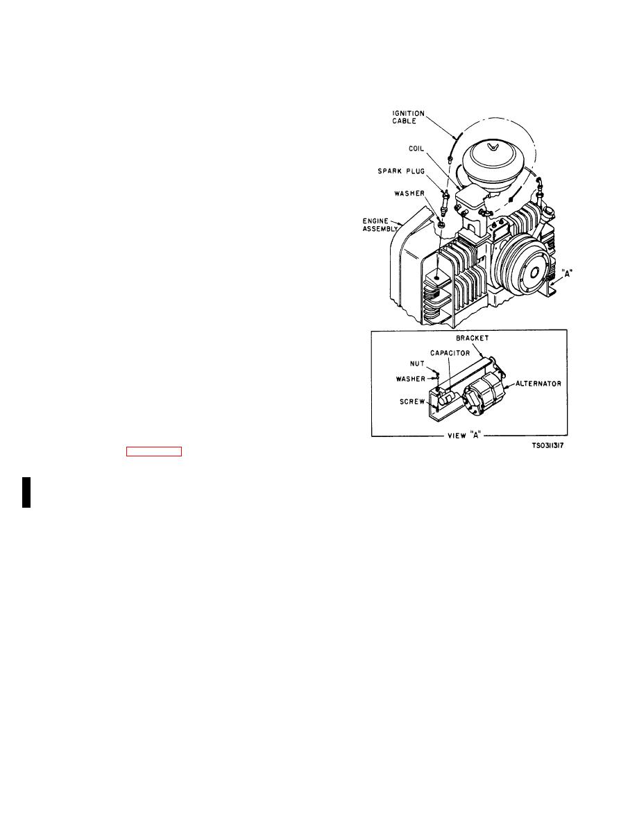
a. Removal (figure 3-8).
(1) Unscrew both ignition cables at the spark
Figure 3-8. Radio Suppression Components (Model
plug and ignition coil. Remove cable from unit.
RMP-J/1-10G)
(2) Unscrew spark plug from engine cylinder
burned points, cracks, or damaged threads. Inspect
head. Remove spark plug and washer
capacitor for damage or breaks. Replace all defective
(3) Disconnect wiring at capacitor
parts
(4) Unscrew nut, washer and screw that
c. Installation.
To install radio suppression
secure capacitor to bracket. Remove capacitor.
components, reverse removal procedure (paragraph 3-
NOTE
19a).
Do not pull on the ignition cable or twist
the braided shield Gently work the cable
3-20.
Testing of Radio Interference Suppression
from side to side and free the rubber
Components.
seal Do not use sharp metal tools to
Test the capacitor for leaks and shorts on a
Install the rubber seals.
capacitor tester, replace defective capacitors. If test
equipment is not available and interference is indicated,
b.
Cleaning and Inspection
isolate the cause of the interference by the trial and error
(1) Clean parts in an approved cleaning
method of replacing the capacitor, spark plug, or ignition
solvent and dry thoroughly.
cable with known good parts In turn until the cause of
(2) Inspect cable for frayed insulation, loose
Interference is located and eliminated.
connectors, or other damage. Inspect spark plug for
Change 3 3-11
|
|
Privacy Statement - Press Release - Copyright Information. - Contact Us |
