 |
|||
|
|
|||
|
Page Title:
Section IX. ENGINE LUBRICATION SYSTEM |
|
||
| ||||||||||
|
|
 TM 5-4110-217-14
sensitivity, shift the adjusting clip toward the governor
shaft. To decrease sensitivity, shift the adjusting clip
toward the linkage end of the governor arm.
(b) Too sensitive a setting will result in a
surging speed (hunting) condition (alternate in-crease
and decrease in engine speed). An opposite setting will
result in too much speed variation between no-load and
full-load conditions. Thus the correct position of the clip
will result in the most stable speed regulation without
causing a surge condition.
(c) Always recheck the speed adjustment
after a sensitivity adjustment. Increasing sensitivity will
cause a slight decrease in speed and will require a slight
increase in the governor spring tension.
(6) Throttle Stop Screw Adjustment (fig.
Figure 3-14. Throttle Screw Adjustment (Model RMP-
Set the throttle stop screw at 1/32-inch from
J/1-10G)
the manifold when the engine is operating with no load
connected.
(5) Sensitivity adjustment.
(a) Governor sensitivity depends upon the
position of the arm end of the governor spring. A sliding
clip provides for adjustment. To increase
Section IX. ENGINE LUBRICATION SYSTEM
becomes pressurized as evidenced by oil leaks at the
3-31.
General.
seals, refer to Direct Support Unit.
The engine has pressure lubrication to all working
parts. The oil system includes the oil intake cup, gear
type oil pump, oil pressure gage, oil filter, and oil
passages to deliver oil throughout the engine. An oil
pressure gage(27, fig. 3-11) is mounted on the engine
blower housing. Normal oil pressure should be 30 psi or
higher when the engine is at operating temperature. If
pressure drops below 30 psi at governed speed, refer to
Direct Support Unit.
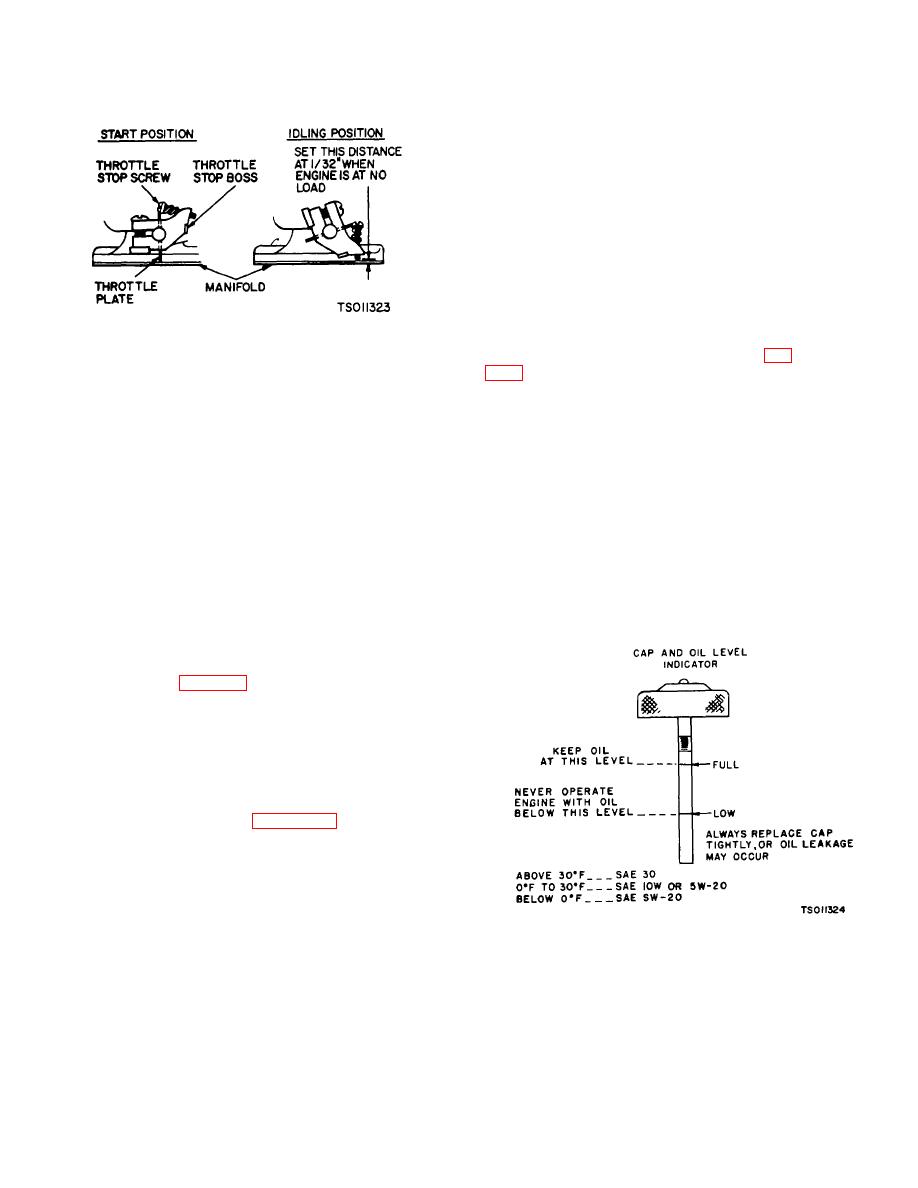
3-32.
Oil Filler and Oil Level Indicator.
The oil fill tube is capped with a cap and oil level
indicator dip-stock. Refer to figure 3-15 for correct oil
level indication. Always replace cap tightly to prevent dirt
from entering the crankcase.
3-33.
Crankcase Breather Tube.
The engine uses a crackcase breather valve for
maintaining crankcase vacuum.
Maintenance is
generally not required. However, if the crankcase
Figure 3-15. Cap and Oil Level Indicator (Model RMP-
J/1-10G)
3-21
|
|
Privacy Statement - Press Release - Copyright Information. - Contact Us |
