 |
|||
|
|
|||
|
Page Title:
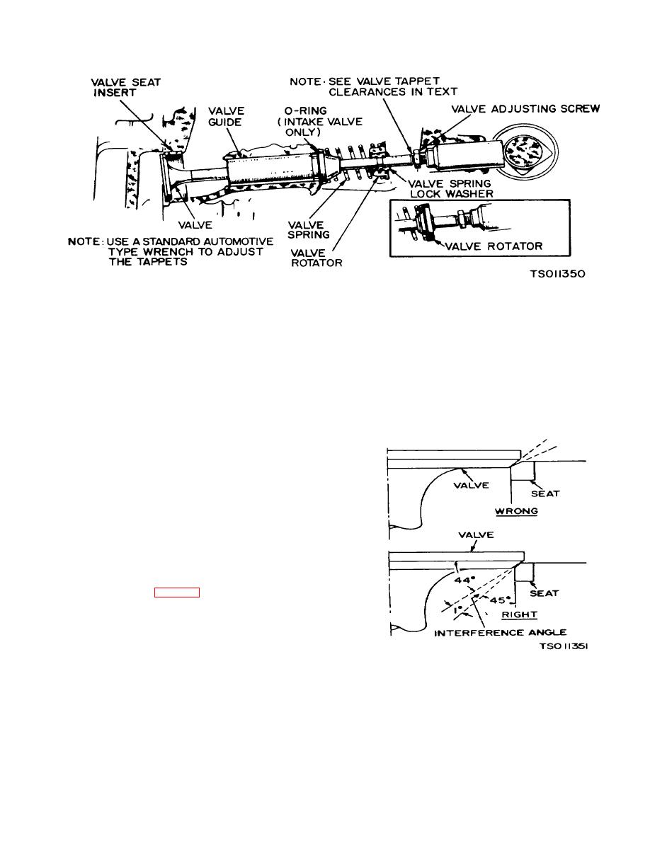
Figure 5-17. Valve System (Model RMP-J/1-lOG) |
|
||
| ||||||||||
|
|
 TM 5-4110-217-14
Figure 5-17. Valve System (Model RMP-J/1-lOG)
e. Remove all grinding compound from engine
e. Remove valves (177) & (178) from crankcase.
f. Remove valve springs (172) & rotators (170) &
parts and place each valve in its proper location.
(171).
Check each valve for a tight seat using an air
g. Worn valve stem guides (174) may be replaced
pressure type testing tool If such a tool is not available,
from inside the valve chamber. A O-ring seal (173) is
make pencil marks at intervals across the valve face and
provided behind the intake valve guides (174) only.
observe if the marks rub off uniformly when the valve is
h. Tappets (168) are also replaceable from the
rotated part of a turn against the seat.
valve chamber, after first removing the valve assemblies.
f Lightly oil the valve stems prior to installation.
5-19. Cleaning and Inspection.
a. Clean all carbon and gum deposits from the
valve, valve rotators, seats, ports, and guides in the
cylinder block with an approved cleaning solvent.
b. Inspect valve springs for set or out-of-round.
Inspect valve rotators and spring washer locks for
damage or wear Replace unrepairable or defective parts.
c. The valve face angle is 44 degrees. The valve
seat angle is 45 degrees. This 1-degree interference
angle results in a sharp seating surface between the
valve and the top of the valve seat. The interference
angle method of grinding valves minimizes face deposits
and lengthens valve life (fig. 5-18).
d. The valves should not be hand lapped, if at all
avoidable, since the sharp contact may be destroyed.
This is especially important where stellite faced valves
and seats are used. Valve faces should be finished in a
machine to 44 degrees. Valve seats should be ground
with a 45 degree stone and the width of the seat band
should be 1/32 to 3-64 of an inch wide. Grind only
enough to assure proper seating.
Figure 5-18. Valve Face and Seat Angles (Model RMP-
J/1-IOG)
5-11
|
|
Privacy Statement - Press Release - Copyright Information. - Contact Us |
