 |
|||
|
|
|||
|
Page Title:
Figure 5-27. Gear Cover & Rear Bearing Plate Oil Seals (Model RM-J/1-10G) |
|
||
| ||||||||||
|
|
 TM 5-4110-217-14
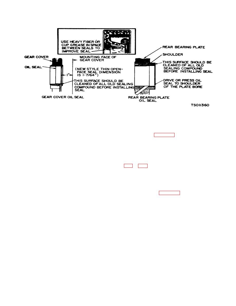
Figure 5-27. Gear Cover & Rear Bearing Plate Oil Seals (Model RM-J/1-10G)
(136), fill the space between the seal with a fibrous
5-27. Gear Cover Oil Seal.
grease or stiff cup grease. This will improve sealing.
Refer to figure 5-27.
a. Removal (fig. S1).
(2) When installing the gear cover oil seal
(1) Remove gear cover assembly (135) (para 5-
(136), tap the seal inward until rear (spring side)of
10).
casing is one inch from the mounting face of the gear
(2) Drive out gear cover oil seal (136) out from
cover. Install new style, thin open face seal, 1-7/64
the inside using gear cover drive tool.
inches from mounting face of cover.
(3) Reassemble engine. Refer to paragraphs
b. Reassembly.
(1) Before installing the new gear cover oil seal
.
Section VIII. CYLINDER BLOCK
and wear with a cylinder bore gauge, telescope gauge or
5-28. Cylinder Block Inspection.
inside micrometer (fig. 5-28). These measurements
should be taken at four places - two at the top and two at
a. Make a thorough check for cracks. Minute
the bottom of piston ring travel.
cracks may be detected by coating the suspected area
d. Record measurements taken lengthwise at the
with a mixture of 25 percent kerosene and 75 percent
top and bottom of the piston travel as follows:
light motor oil. Wipe the part dry and immediately apply
(1) Lengthwise of the block, measure and
a coating of zinc oxide (white lead) dissolved in wood
record as "A" the diameter of the cylinder at the top of
alcohol. If cracks are present, the white coating will
the cylinder where the greatest ring wear occurs.
become discolored at the defective area.
(2) Also, lengthwise of the block, measure and
record as "B" the cylinder diameter at the piston skirt
b. Inspect the cylinder bore for scoring. Check the
travel.
Welsh plugs for a tight, even fit and the fins for
(3) Crosswise of the block, measure and
breakage.
record as "C" the diameter of the top of the cylinder at
the greatest point of wear.
c. Check the cylinder bore for taper, out of round
Change 3 5-17
|
|
Privacy Statement - Press Release - Copyright Information. - Contact Us |
