 |
|||
|
|
|||
|
Page Title:
MUFFLER AND ENGINE EXHAUST SYSTEM (F1000RG-2) |
|
||
| ||||||||||
|
|
 TM5-4110-234-14
TO 40R7-5-7-1
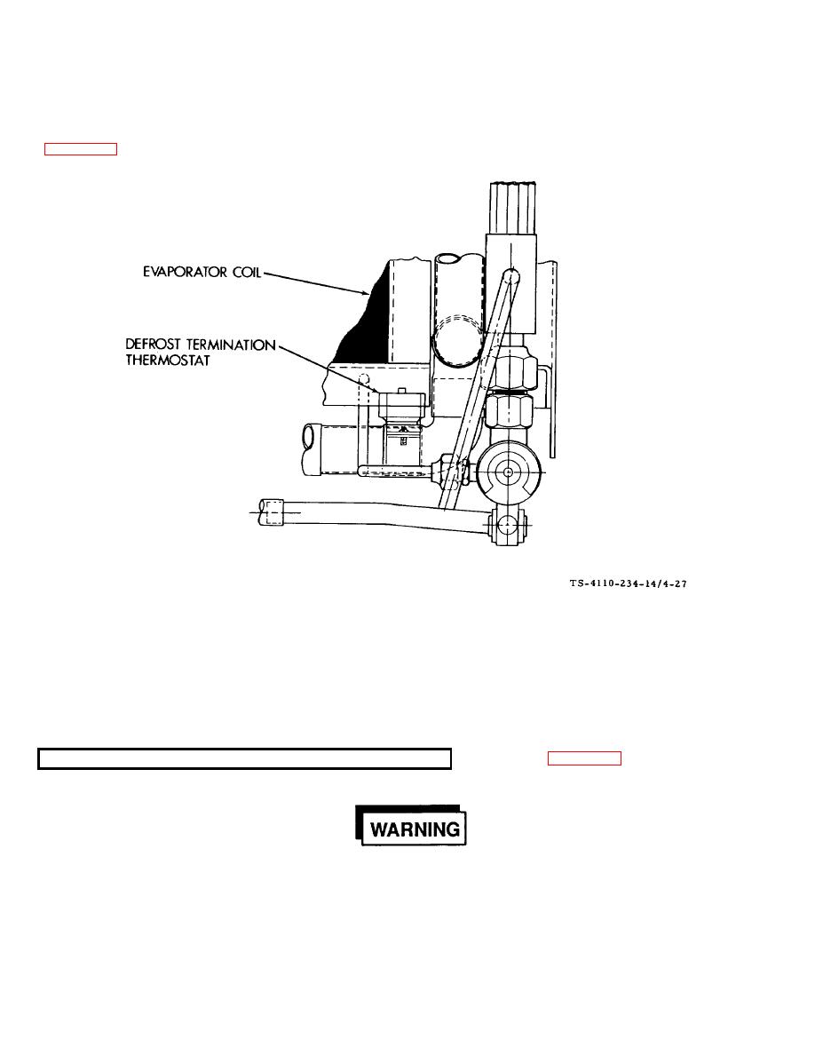
d. Installation.
(1)
Place the thermostat and clamp on the refrigeration tubing below the evaporator coil in the location shown in
figure 4-27. Be sure that the thermostat makes good contact with the tubing. Secure it with two screws and lock nuts.
Figure 4-27. Defrost Termination Thermostat F10000RG-2
(2)
Connect the wire leads. See tags and wiring diagram figure 46.
(3)
Install the evaporator air housing and screen and secure it with 12 screws and lock washers.
(4)
Connect power.
See figure 4-28.
If it is necessary to make adjustments while the engine is running, use extreme caution when close to
hot exhausts, moving parts, etc.
4-69
|
|
Privacy Statement - Press Release - Copyright Information. - Contact Us |
