 |
|||
|
|
|||
|
Page Title:
MOISTURE INDICATING REFRIGERANT SIGHT GLASS |
|
||
| ||||||||||
|
|
 TM5-4110-234-14
TO 40R7-5-7-1
5-21. MOISTURE INDICATING REFRIGERANT SIGHT GLASS See figure 2-3 for functional description and figure 5-5
a.
Removal.
(1)
Pump the system down in accordance with paragraph 5-6.
(2) Connect a dry nitrogen source to the compressor discharge service tee and loosen the flare nut to the
receiver inlet valve. Purge this section of tubing in accordance with paragraph 5-9.
(3)
Debraze (see para 5-12) the tubes to the sight glass and remove the sight glass.
b.
Installation.
(1) Braze (see para 5-12) the tubes to the sight glass.
(2) Tighten the flare nut to the receiver inlet valve and remove the nitrogen source.
(3) Replace the drier (see para 5-19).
(4) Leak test the sight glass area per paragraph 5-7.
(5) Evacuate and charge the system as directed in paragraphs 5-10 and 5-11a.
(6) Close all access doors.
5-22.
a.
Access. Remove the evaporator air housing and screen. (See figure 4-12.)
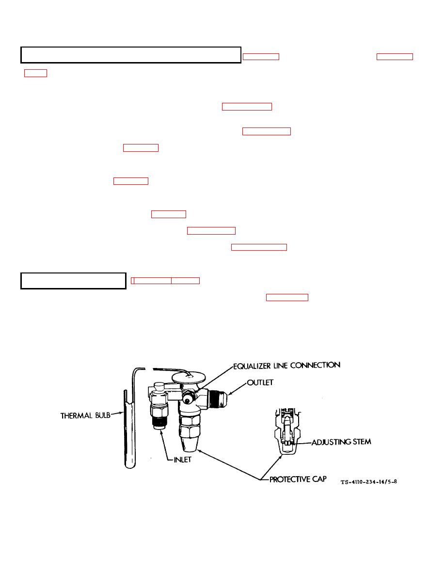
b. Adjust. (See figure 58.) The expansion valve, as supplied with the unit, is preset at the factory. This valve
should not be adjusted unnecessarily. When a new valve is installed or adjustment is necessary, see the following
instructions:
Figure 5-8. Expansion Valve
5-21
|
|
Privacy Statement - Press Release - Copyright Information. - Contact Us |
