 |
|||
|
|
|||
|
|
|||
| ||||||||||
|
|
 TM5-4110-234-14
TO 40R7-5-7-1
(1)
Clean all parts carefully with a dry cloth and compressed air, if available.
(2) Apply 20 weight oil to armature shaft and splines. Use grease sparingly for solenoid starter shift lever pin,
joint of shift lever and plunger, plunger and spacing washers at end of shaft.
(3)
Install the overrunning clutch and the pinion stopper.
(4)
Install the shift lever after replacing the spring holder, lever springs and retainer.
(5)
Install the armature. Use spacing washers to adjust armature end play of 0.004 to 0.020 inch (0.102 to 0.508
mm).
(6)
Install the starter motor thru-bolts.
(7)
Reinstall the solenoid and all wires, while carefully observing the tags on the wires.
(8) When assembling starter to engine oil base, do not draw the mounting bolts up tight. The gears should have
0.004- to 0.007-inch (0.102 to 0.178 mm) backlash. Tap the starter in or out from the oil base to adjust. Then tighten
starter mounting bolts to 30 foot-pounds.
5-37.
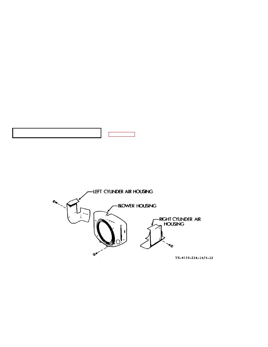
COOLING SHROUD (F10000RG-2) See figure 5-32.
The air-cooling system on the engine consists of heat radiating fins, the flywheel blower, and the cooling shroud
for channeling the airflow. Heat radiating fins are located on the cylinder head and cylinder because the greatest
concentration of heat is in this area. The fins increase the heat radiating surface of these parts allowing the heat to be
carried away more quickly. The flywheel blower consists of air vanes cast as a part of the flywheel. As the flywheel
revolves, these vanes blow cool air across the fins, carrying away the heated air and replacing it with cool air. The shroud
directs the path of the cool air to the areas that demand cooling. It must be in place if the cooling system is to operate at
its maximum efficiency.
Figure 5-32. Cooling Shroud F10000RG-2
a. Replacement. The shroud consists of three parts as figure 532 shows. They are removed or installed by
removing or installing the eight attaching screws.
b.
Repair. Repair is limited to the pounding out of dents. Touch up paint where necessary.
5-49
|
|
Privacy Statement - Press Release - Copyright Information. - Contact Us |
