 |
|||
|
|
|||
|
Page Title:
Figure 5-37. Timing Gear Removal and Installation F10000RG-2 |
|
||
| ||||||||||
|
|
 TM5-4110-234-14
TO 40R7-5-7-1
(1) With the gear cover removed, the governor cup can be taken off after removing the snap ring from the
camshaft center pin. Catch the flyballs while sliding the cup off.
(2) Replace any flyball that is grooved or has a flat spot. If the arms of the ball spacer are worn or otherwise
damaged, replace the entire timing gear set. The governor cup must spin freely on the camshaft center pin without
excessive looseness or wobble. If the race surface of the cup is grooved or rough, replace it with a new one.
(3) When installing the governor cup, tilt the engine so the gear is up, put the flyballs in place and install the cup
and snap ring on the center pin.
(4) The camshaft center pin extends out 3/4 inch (1.91 cm) from the end of the camshaft. This distance
provides an in and out travel distance of 7/32 inches (5.6 mm) for the governor cup as illustrated. Hold the cup against the
flyballs when measuring. If the distance is less (the engine may race, especially at no load), remove the center pin and
press a new pin in for only the required amount. Otherwise, grind off the hub of the cup as required. The camshaft center
pin cannot be pulled outward or removed without damage. If the center pin extends out too far, the cup will not hold the
flyballs properly.
d.
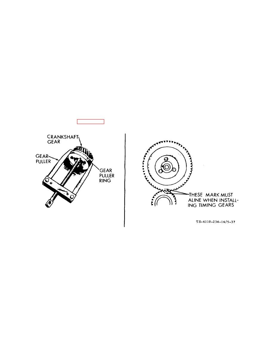
Timing Gears. See figure 5-37.
Figure 5-37. Timing Gear Removal and Installation F10000RG-2
(1) If replacement of either the crankshaft gear or the camshaft gear becomes necessary, install both gears new,
never one only. Use a gear pulling ring to remove the crankshaft gear. Be sure to remove the snap ring first.
(2) The camshaft gear is pressed on and keyed to the camshaft. The camshaft and gear must be removed as
an assembly after first removing the crankshaft gear lock ring and washer. Before removing the camshaft and gear
assembly, remove the cylinder head and valve assemblies. Remove the operating plunger for the breaker points.
Remove the tappets.
(3) The camshaft may be pressed out of the gear by use of a hollow tool or pipe which will fit over the camshaft
center pin. Do not press on the center pin or damage it in any way. The governor ball spacer is a press fit to the camshaft
gear.
(4) When pressing a camshaft gear onto the camshaft, be sure the gear is started straight and that the key is
properly in place. Install the governor cup assembly before installing the camshaft and gear in the engine.
5-53
|
|
Privacy Statement - Press Release - Copyright Information. - Contact Us |
