 |
|||
|
|
|||
|
Page Title:
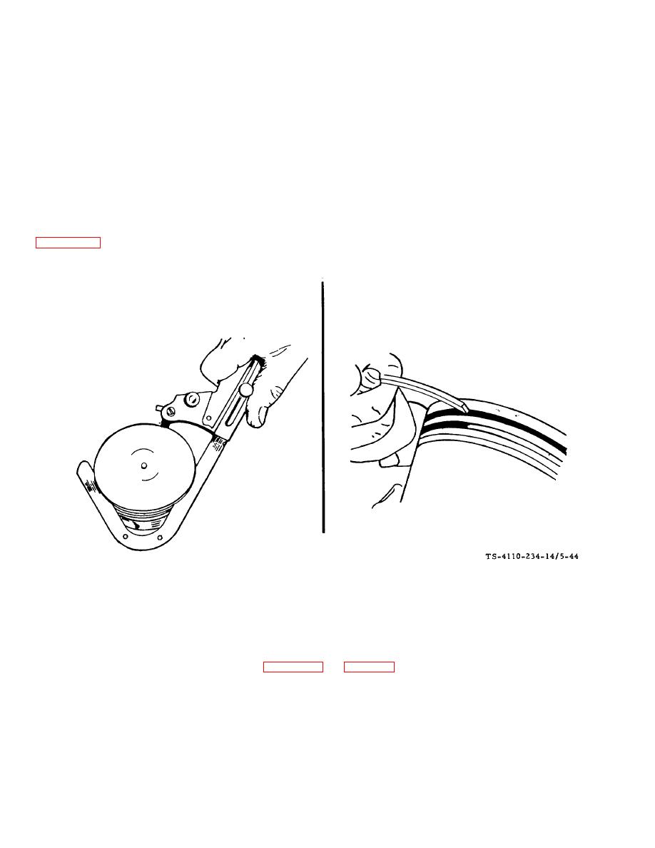
Figure 5-44. Cleaning Piston Ring Grooves F10000RG-2 |
|
||
| ||||||||||
|
|
 TM5-4110-234-14
TO 40R7-5-7-1
(2) To remove the piston and connecting rod assemblies, turn the crankshaft until a piston is at the bottom of the
stroke. Remove the nuts from the connecting rod bolts. Lift the rod bearing cap from the rod and push the rod and piston
assembly out the top of the cylinder with the handle end of a hammer. Be careful not to scratch the crankpin or the
cylinder wall when removing these parts.
NOTE
Keep the connecting rod bearing caps and bearings with their respective rods.
(3) The pistons are fitted with two compression rings and one oil control ring with an expander. Remove these
rings from the piston using a piston ring spreader.
(4) Clean the piston ring grooves with a groove cleaner or the end of a broken ring filed to a sharp point. See
figure 5-44. All passages should be cleaned with a non-caustic solvent. Clean the rod bore and the back of the
connecting rod bearings thoroughly.
Figure 5-44. Cleaning Piston Ring Grooves F10000RG-2
(5) Mark each piston to make sure the rod will be assembled on the piston from which it was removed. Remove
the piston pin retainer from each side and push the pin out.
(6) Inspect the pistons for fractures at the ring lands, skirts and pin bosses. Check for wear at the ring land
using new rings and a feeler gage as shown in figure 5-45. See Table 5-3 for proper side clearance measurement.
(7) Improper width rings or excessive ring side clearance can result in ring breakage. New rings in worn ring
grooves do not have good cylinder wall contact. See figure 546.
5-59
|
|
Privacy Statement - Press Release - Copyright Information. - Contact Us |
