Order this information in Print

Order this information on CD-ROM

Download in PDF Format


Click here to make tpub.com your Home Page

Page Title: figure 4-17. Control module connector knob and bulb mounting.
Back | Up | Next

Click here for a printable version

Google


Web
www.tpub.com

Home


Information Categories
.... Administration
Advancement
Aerographer
Automotive
Aviation
Combat
Construction
Diving
Draftsman
Engineering
Electronics
Food and Cooking
Math
Medical
Music
Nuclear Fundamentals
Photography
Religion
USMC
   
Products
  Educational CD-ROM's
Printed Manuals
Downloadable Books


4-44.  R e m o v a l 
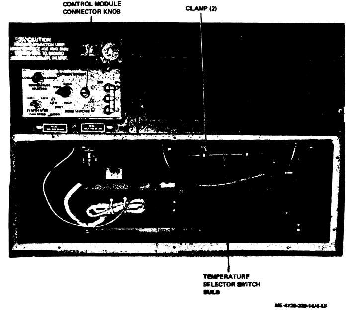
b.  Refer   to   figure   4-17  and   disengage   tem- a.  Refer  to  paragraph  4-18  and  remove perature   selector   switch   bulb   from   clamps   by evaporator   air   inlet   louver. loosening   clamp   screws. figure   4-17.   Control   module   connector   knob   and   bulb   mounting. c.  Turn   connector   knob   (fig.   4 - 1 7 )     c o u n- temperature   selector   switch ter   clockwise   until   screw   is   disengaged   and   pull bottom   of   junction   box. control   module   from   junction   box.   Carefully   pull bulb   through   slot   in 4-26

Privacy Statement - Press Release - Copyright Information. - Contact Us - Support Integrated Publishing

Integrated Publishing, Inc. - A (SDVOSB) Service Disabled Veteran Owned Small Business