|
| |
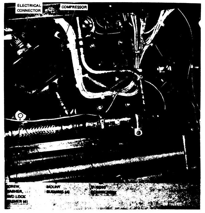
figure 5-2. Compressor. removal and installation.
(6) Lift compressor from air conditioner.
Caution: If compressor is being replaced
b e c a u s e o f a m o t o r b u r n o u t , d e c o n t a m i n a te
system as instructed in paragraph 6-5. Failure
of the replacement
compressor
will
result
if
all
the contaminates are not removed.
c. Installation. Refer to figure 5-2 and install
compressor as follows:
(1) Place compressor on mounts and install
four compressor mount bushings. Secure com
pressor with four screws, washers and lock washer
(2) Connect tubing.
(3) Connect electrical connector.
( 4 ) R e f e r t o p a r a g r a p h 4 - 2 1 a n d i n s t a ll
housing top covers.
(5) Refer to paragraph 6-3 and discharge the
refrigerant system.
5 - 6
|