|
| |
(3) Check for shorts between one terminal and
b. Removal. With junction box removed, refer to
transformer case and also between one primary
figure 4-21 and remove four screws and lock
terminal and one secondary terminal using an
washers. Disconnect and remove transformer.
insulation tester, megger or multimeter on high
ohms setting. Replace transformer if a short is
indicated.
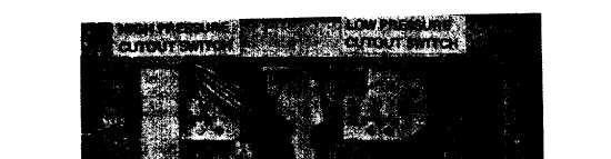
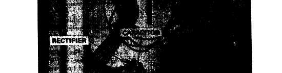
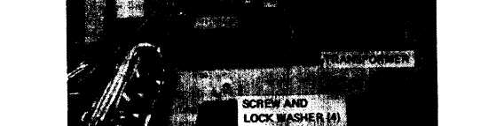
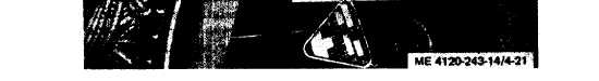
Figure 4-21. Transformer, rectifier and pressure switches.
c. Installation. Refer to figure 4-21 and install
transformer, four screws, and four lock washers.
Connect leads. Refer to paragraph 4-54 and install
junction box.
4-57.Rectifier
a. Removal. Remove rectifier as follows:
(1) Refer to paragraph 4-50 and remove
junction box.
(2) Refer to figure 4-21 and remove filter
capacitor. Disconnect leads.
(3) Remove two cap screws and remove
rectifier.
b. Testing. Apply a 30 volt ac source of power
across the No.1 and 3 terminals. Check for 24 to 28
volt dc output across terminals 2 and 4. Replace
rectifier if defective.
4-34
c. Installation. Refer to figure 4-21 and install
rectifier as follows:
(1) Install rectifier and two cap screws.
(2) Connect leads and install capacitor.
(3) Refer to paragraph 4-54 and install
junction box.
4-58. High and Low and Pressure Cutout
Switches
a. General. The high and low pressure cutout
switches cannot be removed without opening the
refrigeration system. Electrical tests should be
made with the switches installed.
b. Testing. Test switches as follows:
(1) Refer to paragraph 4-50 and remove
junction box.
(2) Disconnect leads and test for continuity
|