|
| |
(5) Disconnect tubing from evaporator coil as
(6) Refer to paragraph 4-21 and install
required.
housing top covers.
(6) Remove six screws and lock washers and
(7) Refer to paragraph 6-3 and charge the
lift evaporator coil and angle from air conditioner.
refrigerant system.
Angle is connected to coil with four blind rivets.
5-19. Condenser Louver Actuator and Control
b. Installation. Install evaporator coil as follows:
(1) If angle figure 5-3 was removed from coil,
secure angle to coil with four rivets.
(2) Install coil in air conditioner and secure
coil to brackets with six screws and lock washers.
(3) Connect tubing to coil
(4) Install loop clamp and screw.
(5) Refer to paragraph 4-18 and install
evaporator air outlet louver.
a. Removal. Remove actuator and push-pull
control as follows:
(1) Refer to paragraph 6-3 and discharge the
refrigerant system.
(2) Refer to paragraph 4-21 and remove
housing covers.
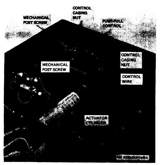
(3) Refer to figure 5-4 and loosen mechanical
post screws to loosen control wire.
Figure 5-4. Condenser louver control and actuator cylinder.
(4) Remove control casing outer nuts at each
condenser guard. Refer to figure 5-5 and remove
end and remove push-pull control.
five screws and lock washers that secure condenser
(5) Disconnect elbow swivel nut from end of
air discharge louver assembly to housing. Remove
actuator cylinder.
two screw base studs and louver assembly.
(6) Refer to paragraph 4-20 and remove
5-7
|