Order this information in Print

Order this information on CD-ROM

Download in PDF Format


Click here to make tpub.com your Home Page

Page Title: Figure 18. Control BO X, Rotary Control Switch And Thermostat, Removal And In- stallation
Back | Up | Next

Click here for a printable version

Google


Web
www.tpub.com

Home


Information Categories
.... Administration
Advancement
Aerographer
Automotive
Aviation
Combat
Construction
Diving
Draftsman
Engineering
Electronics
Food and Cooking
Math
Medical
Music
Nuclear Fundamentals
Photography
Religion
USMC
   
Products
  Educational CD-ROM's
Printed Manuals
Downloadable Books


TM 5-4120-259-15 STEP   1. 
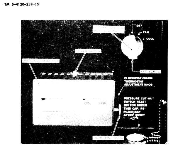
REMOVE   SET   SCREW   FROM   ROTARY   CONTROL   SWITCH   KNOB   AND   REMOVE   KNOB.   REMOVE RETAINER   NUT   FROM   SWITCH.
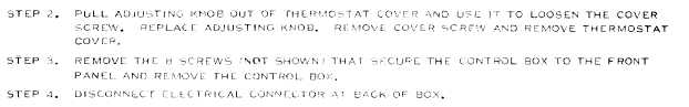
 STEP  5. REMOVE  8  SCREWS  AT  BACK  OF  BOX  AND  REMOVE  BACK  COVER  FROM  CONTROL  BOX. Figure   18.   Control   BO X,   Rotary   Control   Switch   And   Thermostat,   Removal   And   In- stallation. they   are   soldered   to   the   harnesses.   Replace- 68.  Evaporator  Drain  Hose  and ment   harnesses   include   all   necessary   connec- Connection tors,   disconnect   parts,   terminals,   and   switches, Remove   and   install   the   evaporator   drain completely   fastened   in   place   on   the   wires. hose   and   connection   as   shown   by   figure   26. 30

Privacy Statement - Press Release - Copyright Information. - Contact Us - Support Integrated Publishing

Integrated Publishing, Inc. - A (SDVOSB) Service Disabled Veteran Owned Small Business