 |
|||
|
|
|||
|
Page Title:
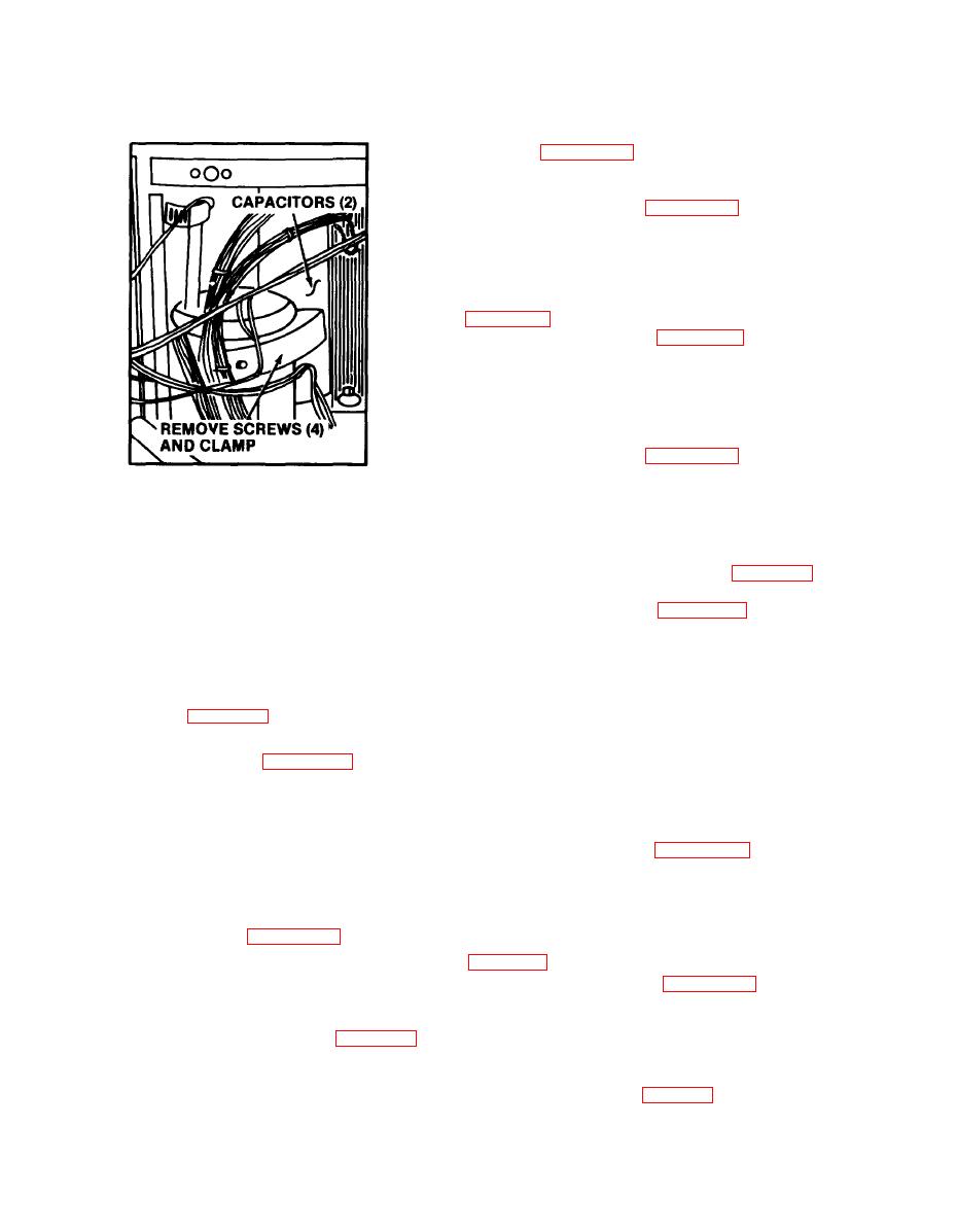
Figure 3-10. Capacitor removal and installation. |
|
||
| ||||||||||
|
|
 TM 5-4120-273-15
Electrical Heater Relay
tion box, figure 3-13. A motor relay starts the
compressor motor and a heater relay is connected
to the electrical heaters.
relays.
c. Inspection and Testing.
(1) Inspect for pitted or burned contacts.
(2) Test for continuity across coil with mul-
timeter set on OHMS. Refer to wiring diagram
stall relays.
3-38. Rectifier
a. General. The rectifier changes alternating
current to direct current.
rectifier.
NOTE: TAG AND DISCONNECT
ELECTRICAL LEADS AS
c. Inspection and Testing.
NECESSARY.
(1) Inspect for cracked or broken casing and
burned or damaged contacts.
ME 4120-273-15/3-10
(2) Test for continuity with multimeter set
on OHMS. Refer-to wiring diagram figure 1-5 to
establish points of continuity.
rectifier.
3-39. Heater Elements
c. Testing. Test the circuit breaker for continu-
ity with a multimeter set on OHMS. Refer to the
mounted directly behind the evaporator coil. These
wiring diagram figure 1-5 for points to establish
heaters provide the heat called for by the thermo-
continuity.
stat to maintain the required temperature of the
conditioned air. The heaters provide two ranges
of heating and are manually controlled by placing
circuit breaker.
the selector switch in the proper position (LO-
HEAT or HI-HEAT) to maintain the required
temperature.
CV-6-3-08-400 only)
a. General. The phase sequence relay prevents
remove the heater elements.
operation of the unit unless the phase sequence is
c. Inspection and Testing.
correct and the fan and compressor motor rotate
(1) Inspect for broken or damaged elements.
in the proper direction.
(2) Test for continuity across elements with
multimeter set on OHMS. Refer to wiring diagram
phase sequence relay.
c. Inspection and Testing.
(1) Inspect for cracked or broken casing.
install heating elements.
(2) Test for continuity with multimeter set
on OHMS. Refer to wiring diagram figure 1-5 to
establish points of continuity.
a. General. The high pressure switch prevents
d. Installation. Refer to figure 3-18 and install
the compressor from operating if the head pres-
the phase sequence relay.
sure exceeds 445 psig (fig. 3-14).
|
|
Privacy Statement - Press Release - Copyright Information. - Contact Us |
