|
| |
b. Removal. Remove the intake grille (fig
3-4). Refer to figure 3-5 and remove the air con-
ditioning filter.
c. Servicing. Refer to figure 3-1 and service the
denser coil grille and screen.
d. Installation. Install the air conditioning
filter in reverse order of removal.
3-8. Evaporator and Condenser Coil
Service
a. Removal.
(1) Refer to figure 3-6 and remove the con-
denser coil grille and screne.
(2) Refer to paragraph 3-6 and remove the
mist eliminator.
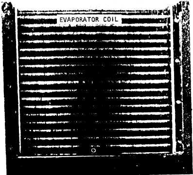
b. Se-icing. Refer to figure 3-2 and service the
evaporator and condenser coils
c. Installation. Install the condenser coil grille
and screen (para 3-22. Install the mist elimina-
tor (para 3-6).
3-9 Fuse Replacement
a. General. Three fuses are mounted in the
upper right corner of the junction box in two sep-
arate fuse holders. Fuse holder XF1 contains two
lo-ampere fuses and fuse holder XF2 contains
one 5-am, refuse.
b. Removal
(1) Refer to figure 3-4 and remove the front
access cover.
(2) Refer to figure 3-12 and remove the
junction box cover.
(3) Refer to figure 3-13 and remove fuses
(4) Test fuse for continuity with multime-
ter.
c. Installation
(1)
ampere
(XF2)
(2)
(3)
Refer to figure 3-13 and install two 10-
fuses (XF1) and one 5-ampere fuse
Install junction box cover (fig. 3-12)
Install front access cover (fig. 3-4).
STEP
STEP
1.
CLEAN SURFACE OF COIL WITH A SUITABLE BRUSH.
2.
CLEAN BETWEEN FINS WITH LW-PRESSURE COMPRESS
BOTE:
SERVICE CONDENSER COIL IN A SIMILAR MANNER.
ME 4120~308-15/j-2
Figure 3-2. Servicing evaporator and condenser coils
IED AIR.
3-3
|