|
| |
Figure 3-10-Continued
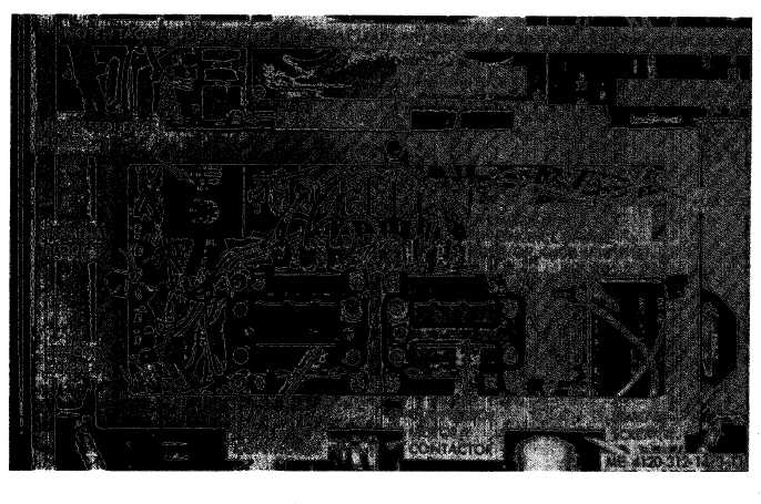
Figure 3-11. Control box assembly and components, removal and installation.
for points to establish contact. Continuity should
exist across to terminals of the switch when the
temperature is above plus 50°F.
d. Installation. Install the outdoor thermostat,
fan, and fan guard by reversing the order of re-
moval.
3-34. Fuse Service
a. General. There are two 5-ampere fuses in the
upper right hand corner of the control box.
b. Removal. Remove
(para 3-6) and control
3-26) .
the front access panel
box front panel (para
3-35. Electric Heater Thermostat
a. Testing. Tag and disconnect the leads and
test for continuity with a multimeter set on the
ohm scale. Refer to the applicable wiring dia-
gram (fig. 1-3 or 1-4) for the contact points.
b. Removal. Refer to figure 3-13 and remove
the electric heater thermostat.
c. Installation. Install the thermostat by rev-
ersing the order of removal.
3-36. Electric Heater Elements
a. General. The two banks of electrical resist-
3-17
|