|
| |
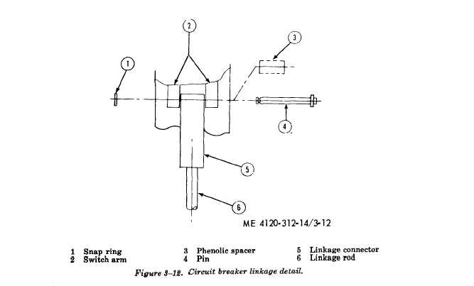
Figure 3-12
ante heaters are mounted directly behind the eva-
porator coil. These heaters provide the heat
called for by the temperature control to maintain
the desired heat. The two banks of heaters prov-
ide two ranges of heating and are manually con-
trolled by the selector switch.
b. Removal.
(1) Remove the top cover of unit (para
3-6).
(2) Refer to figure 3-14 and remove the
electric heater elements.
c. Installation. Install
ments by reversing the order of removal. When
the electric heater ele-
installing, be sure the heater element is inserted
into the bottom retaining clip.
3-37. High Pressure Cutout Switch Testing
Procedure
Test the switch for continuity with a multimeter
set on the ohm scale. Refer to the wiring diagram
(fig. 1-3) for contact points. If no continuity is
indicated, push the reset button.
3-18
|