 |
|||
|
|
|||
|
|
|||
| ||||||||||
|
|
 TM5-4120-347-14
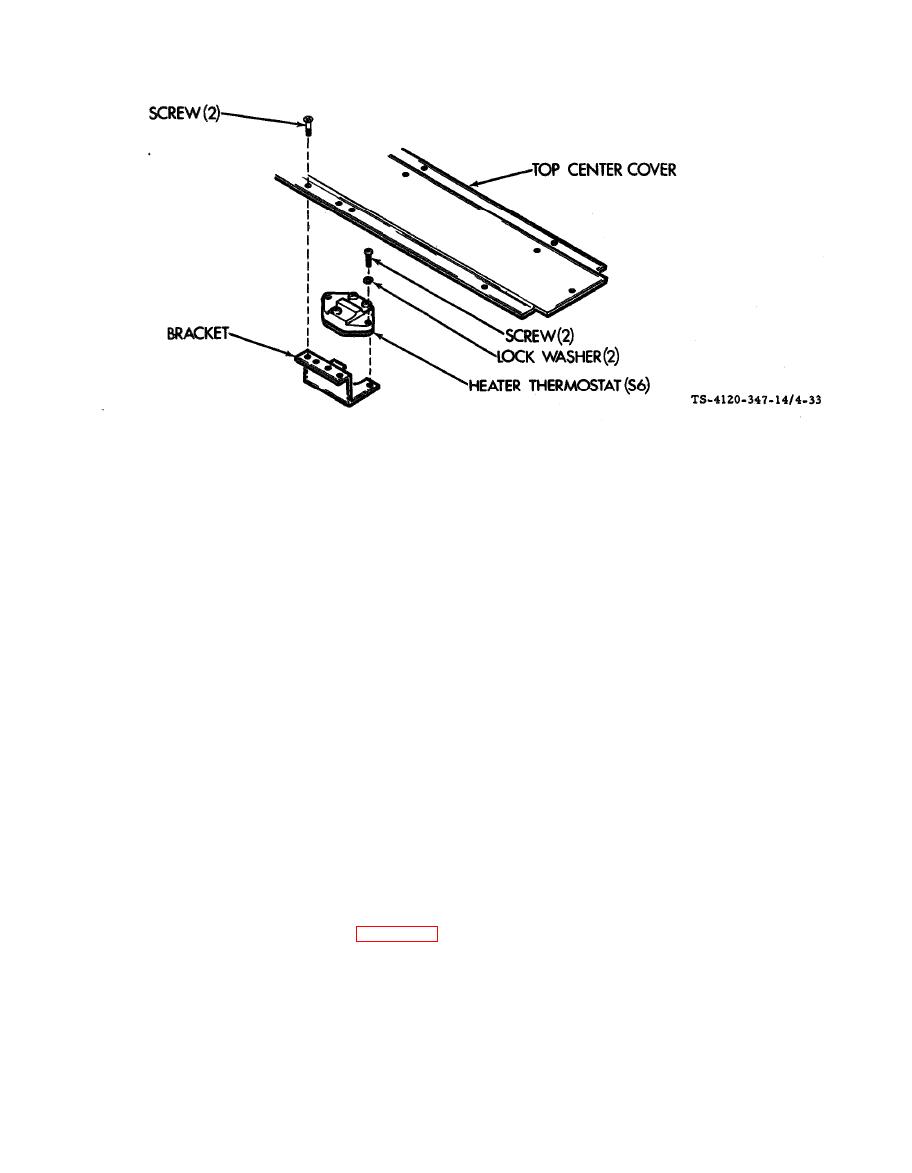
b. Inspect/Test.
(1) Inspect for cracks, loose connections and obvious damage. Replace if defective.
(2) Remove the two screws and pull the thermostat from the bracket.
(3) Tag and disconnect leads.
(4) Using a multimeter check continuity on terminals 1 and 2 of the thermostat. Continuity should be
indicated.
(5) Repeat step (4) with meter connected to terminals 3 and 4.
(6) Tape the bulb of a thermometer or junction of a thermocouple to the body of the heater thermostat,
and connect the multimeter to terminals one and two. Use a 150 watt lamp bulb or a heat source. Gradually
apply heat while observing both the thermometer and the multimeter. Continuity should dropout at 145 to 155
F (63 to 68o C). Remove heat source and let the thermostat cool while observing the thermostat and multimeter.
Continuity should be re-establishd ed 100 to 120 F (38 to 49oC).
(7) Repeat step (6) with meter connected to terminals 3 and 4.
(8) If the thermostat does not meet the above requirements replace it.
c. Installation.
(1) See tags and wiring diagram figure 4-5 and connect leads. Remove the tags.
(2) Attach the thermostat to the bracket with two screws and lock washers,
(3) Attach the thermostat and bracket assembly to the flange of the top center cover with two screws.
(4) Install the top front cover.
(5) Connect power at the power source.
4-69
|
|
Privacy Statement - Press Release - Copyright Information. - Contact Us |
