 |
|||
|
|
|||
|
Page Title:
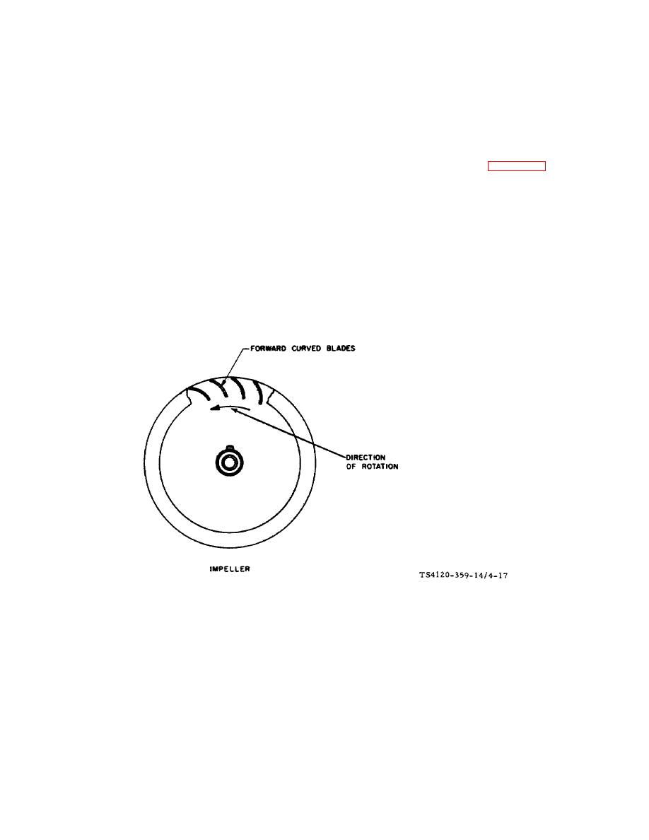
Figure 4-17. Fan Impeller Direction of Rotation |
|
||
| ||||||||||
|
|
 TM 5-4120-359-14
(7) If the other fan is to be removed, go back to step 1.
b. Inspection
(1) Check that impeller is in good condition. Replace if it is out of round, dented, broken or if the hub is loose.
(2) Check to see that the setscrew is not missing.
(3) After the impellers are installed, check to see that the rotation is correct. (See figure 4-17 in installation
instructions.)
c.
Installation/Alinement
(1) Place blower assembly on a flat surface with discharge openings down and outside inlet rings and impellers
removed.
(2) Aline impeller setscrew with flat surface on extension shaft.
(3) Slip impeller on extension shaft as far as possible and tighten setscrew.
(4) Be sure that the direction of rotation arrows on motor and fans agree. Take care that impellers are not
reversed.
Figure 4-17. Fan Impeller Direction of Rotation
(5) Slip impeller and extension shaft assembly on motor shaft.
(6) Install the outer fan inlet ring.
(7) Aline setscrews on extension shaft with flat surface on motor shaft.
(8) Position the impeller an equal distance between the two inlet rings.
(9) Using allen wrench, tighten the two setscrews.
4-55
|
|
Privacy Statement - Press Release - Copyright Information. - Contact Us |
|
|
Integrated Publishing, Inc. - A (SDVOSB) Service Disabled Veteran Owned Small Business
|

