 |
|||
|
|
|||
|
Page Title:
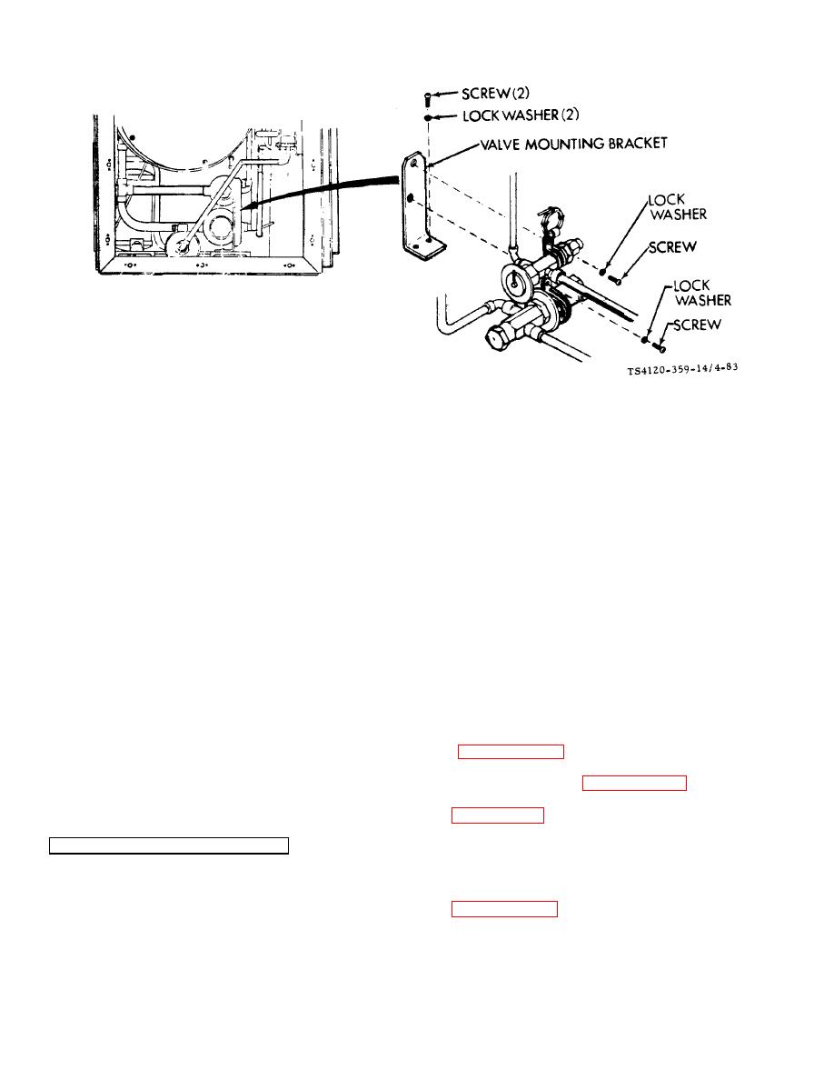
Figure 4-83. Valve Mounting Bracket |
|
||
| ||||||||||
|
|
 TM 5-4120-359-14
Figure 4-83. Valve Mounting Bracket
b. Removal
(1) Using screwdriver, remove two screws and lock washers from the valve and capillary clamps.
(2) Using offset screwdriver, remove two screws from the base of bracket.
(3) Remove bracket from unit.
c.
Installation
(1) Position bracket in unit and aline base mounting holes.
(2) Using offset screwdriver, secure bracket to housing with two screws and lock washers.
(3) Using screwdriver, secure clamps to bracket with two screws and lock washers.
NOTE
Upper screw and lock washer secures both capillary and expansion valve clamps.
Follow-on Procedures: 1. Install right end condenser cover. (See paragraph 3-26.)
2. Install condenser section electrical module assembly. (See paragraph 4-90.)
3. Install air conditioner on shelter. (See paragraph 3-6.)
4-80. HIGH PRESSURE SWITCH (S4)
Preliminary Procedures:
1. Disconnect power.
2. Remove top condenser cover. (See paragraph 3-25.)
4-165
|
|
Privacy Statement - Press Release - Copyright Information. - Contact Us |
|
|
Integrated Publishing, Inc. - A (SDVOSB) Service Disabled Veteran Owned Small Business
|

