 |
|||
|
|
|||
|
Page Title:
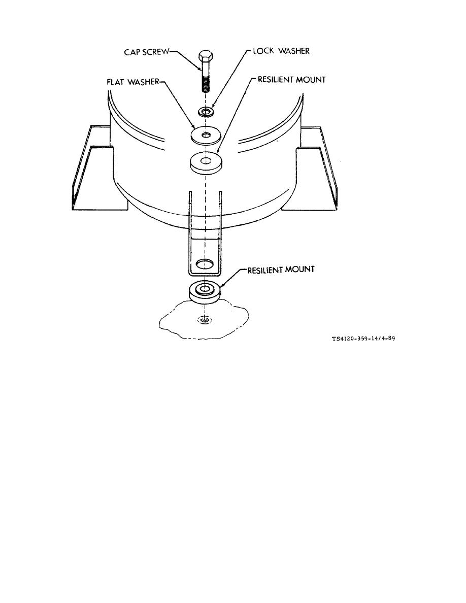
Figure 4-89. Resilient Mounts, Compressor |
|
||
| ||||||||||
|
|
 TM 5-4120-359-14
Figure 4-89. Resilient Mounts, Compressor
b. Removal/Installation
(1) Using socket, extension, and ratchet; remove four cap screws, lock washers, flat washers, and resilient
mounts from top of compressor mounting feet.
(2) Replace resilient mounts that are under the compressor feet, one at a time.
(3) Tilt compressor high enough to slide resilient mount out from under foot.
NOTE
The smaller diameter necked portion of the resilient mount goes toward
compressor foot.
(4) With the smaller diameter (necked portion) of the resilient up, slide the resilient mount back under the
compressor foot. The necked portion should fit into hole in compressor foot.
4-177
|
|
Privacy Statement - Press Release - Copyright Information. - Contact Us |
|
|
Integrated Publishing, Inc. - A (SDVOSB) Service Disabled Veteran Owned Small Business
|

