 |
|||
|
|
|||
|
|
|||
| ||||||||||
|
|
 TM 5-4120-359-14
(5) Repeat steps (3) and (4) above on remaining three resilient mounts, if they are to be replaced.
(6) Place four top resilient mounts necked portion down into holes in compressor feet.
(7) Using socket, extension, and ratchet, secure the compressor with four cap screws, lock washers, and flat
washers.
(8) To obtain proper loading, tighten cap screw until contact is made with all parts. Then, turn cap screw head 2
1/2 to 3 1/2 more turns.
Follow-on Procedures: 1. Install left end condenser cover. (See paragraph 3-27.)
2. Install top condenser cover. (See paragraph 3-25.)
3. Install air conditioner on shelter. (See paragraph 3-6.)
4-88. COMPRESSOR
Preliminary Procedures:
1. Remove air conditioner from shelter. (See paragraph 3-6.)
2. Remove top condenser cover. (See paragraph 3-25.)
3. Remove left end condenser cover. (See paragraph 3-27.)
a. Inspect/Test
WARNING
Disconnect input power to the air conditioner before performing any maintenance
to the electrical system. Voltages used can be lethal. Shutting the unit off at the
control module does not disconnect power to the compressor heater.
(1) Be sure power has been disconnected from air conditioner.
(2) Electrically test the heater element heater thermostat, wiring harness, and motor as follows.
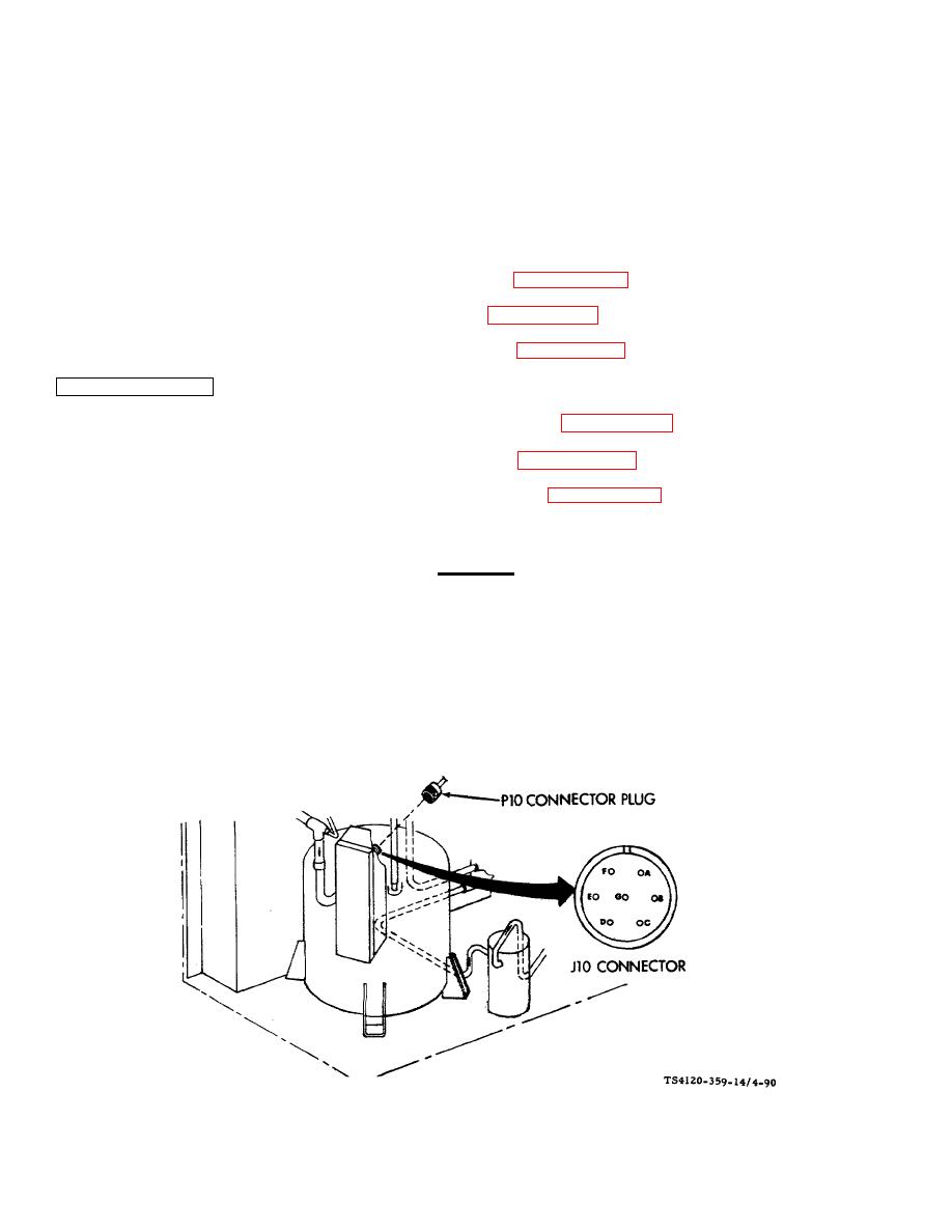
(3) Disconnect wiring harness at connectors P10 and J10 (located on the compressor junction box).
Figure 4-90. Compressor Electrical Test
4-178
|
|
Privacy Statement - Press Release - Copyright Information. - Contact Us |
|
|
Integrated Publishing, Inc. - A (SDVOSB) Service Disabled Veteran Owned Small Business
|

