|
| |
TM 5-4120-361-14
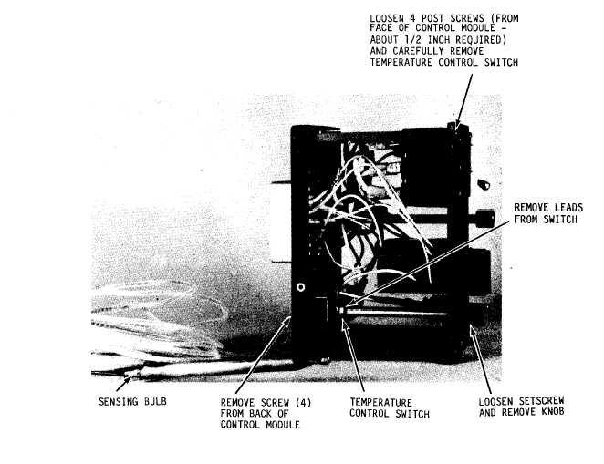
Figure 4-13.
Temperature control
(c) Installation.
(i) Refer to figure 4-14 and
install the control circuit breaker.
(ii) Refer to figure 4-10 and
install the control module.
4-27.
Junction Box Components.
a.
General.
The junction box compo-
nents consist of the following:
time
delay relay, evaporator fan motor low
speed relay, fixed heater relay, cycling
heater relay, evaporator fan motor high
speed relay, condenser fan motor high
speed relay, condenser fan motor low
speed relay, compressor relay, and
terminal boards.
switch,
b.
moving
removal and installation
Inspection and Test.
Before re-
any of the junction box compo-
nents check for loose connections,
pitted contacts, and cracked or broken
casings.
Refer to wiring diagram (fig-
ure 1-5) and check for continuity with a
multimeter.
If no continuity exists, or
a casing is broken or cracked, replace
the component.
(1) Time Delay Relay.
(a) Testing.
Turn mode selector
switch to cool and note time lapse be-
tween starting of fan motors and start-
ing of compressor.
If time lapse is
less than 27 seconds or more than 33
seconds, replace the relay.
4-22
|