Order this information in Print

Order this information on CD-ROM

Download in PDF Format


Click here to make tpub.com your Home Page

Page Title: Figure 4-14. Evaporator fan motor speed switch and control circuit breaker, removal and installation
Back | Up | Next

Click here for a printable version

Google


Web
www.tpub.com

Home


Information Categories
.... Administration
Advancement
Aerographer
Automotive
Aviation
Combat
Construction
Diving
Draftsman
Engineering
Electronics
Food and Cooking
Math
Medical
Music
Nuclear Fundamentals
Photography
Religion
USMC
   
Products
  Educational CD-ROM's
Printed Manuals
Downloadable Books


TM  5-4120-361-14 (b)  Removal. (i) Refer to figure 4-10 and remove the junction box. (ii) Refer to figure 4-15 and remove the time delay relay. (c)  Installation. (i) Refer to figure 4-15 and install the time delay relay. (2) Evaporator Fan Motor Low Speed Relay. (a)  Removal. (i) Refer to figure 4-10 and remove the junction box. (ii) Refer to figure 4-15 and remove the evaporator fan low speed re- lay. (b)  Testing. Check for loose connections  and   cracked or broken cas- ing. Check for continuity with a multi- meter. If no continuity exists, or if (ii) Refer to figure 4-10 and install the junction box.
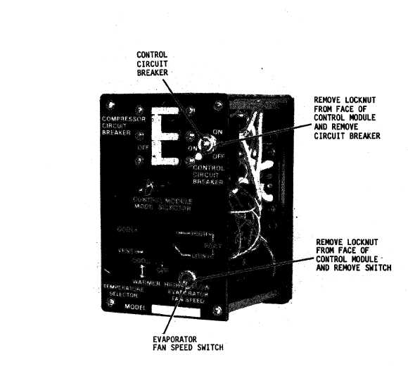
 Figure  4-14. Evaporator fan motor speed switch and control circuit breaker, removal and  installation 4-23

Privacy Statement - Press Release - Copyright Information. - Contact Us - Support Integrated Publishing

Integrated Publishing, Inc. - A (SDVOSB) Service Disabled Veteran Owned Small Business