|
| |
TM5-4120-376-14
4-22. JUNCTION BOX AND CONTROL MODULE ASSEMBLY/Inspect, Test, Replace (Cont)
LOCATION/ITEM
Removal:
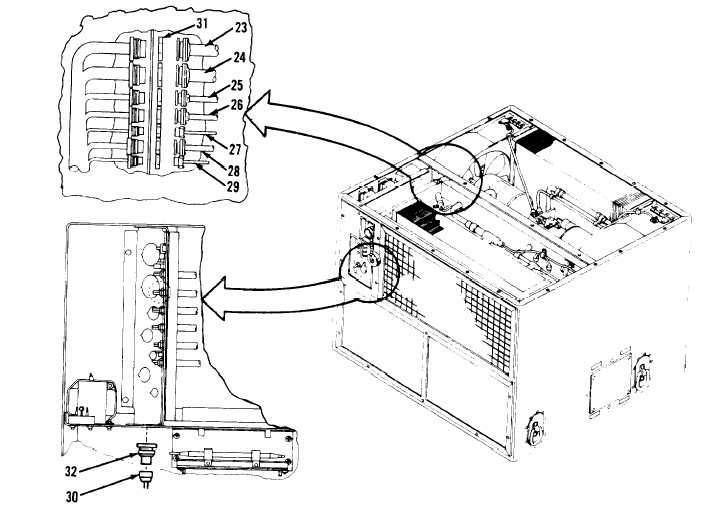
Junction Box
CAUTION
Be careful when removing junction box not to damage plastic relay covers.
1. Remove six screws (21) and six lock washers (22) securing junction box (20) to housing.
2. Pull junction box (20) out to allow access to connectors.
3. Disconnect junction box wire harness connectors P-n (23), P-7 (24), P-4 (25), P-5 (26),
P-10 (27), P-9 (28), P-8 (29) and P-3 (30).
4. Remove retaining nuts (31) securing electrical connectors J-11, J-7, J-4, J-5, J-10, J-9,
J-8 and retaining nut (32) on J-3, to bulkhead.
4-109
|