|
| |
TM5-4120-376-14
4-22. JUNCTION BOX AND CONTROL MODULE ASSEMBLY/hspect, Test, Replace (Cont)
LOCATION/ITEM
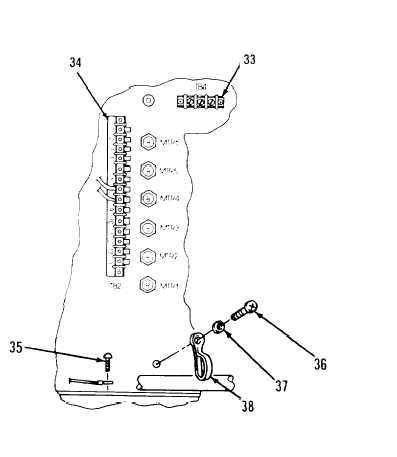
Removal:
5. Tag and remove wiring from
TB-4 (33) TB-2 (34) and ground
E-3 (35).
6. Remove one screw (36) and
one washer (37) securing one clamp
(38) and wire harness to housing.
7. Remove clamp (38) and junc-
tion box.
Terminal Board TB3
1. Remove two screws (39) two
flat washers (40) and two lock
nuts (41) securing terminal board
TB3 (42) and marker strip (43)
to junction box.
2. Tag and remove wires from
terminals.
3. Remove terminal board TB3.
Terminal Board TB1
1. Remove four screws (44) four
flat washers (45) and four lock nuts
(46) securing terminal board TB1 (47)
and marker strip (48) to junction box.
2. Tag and remove wires from terminals.
3. Remove terminal board TB1.
Relay K3
1. Remove four screws (49) four flat washers (50) and four lock nuts (51) securing relay K3
(52) to junction box.
2. Tag and remove wires from terminals.
3. Remove relay K-3.
4-110
|