|
| |
TM5-4120-376-14
4-23. AMBIENT THERMOSTAT AUXILIARY POWER INLET/inspect, Test, Repair, Replace
(Cont)
LOCATION/ITEM
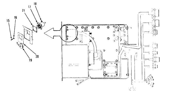
Installation:
1. Attach wires to appropriate terminals on terminal board (22) and on ground screw (23) in
accordance with Appendix E and remove tags.
2. Align inlet power connector assembly (J-1) (18) gasket (21) plate (20) and connector cover
(19) with holes in junction box (14).
3. Secure inlet power connector assembly (J-l), gasket and cover to junction box with four
screws (15) four flat washers (16) and four lock nuts 5(17).
4. Install junction box in accordance with
5. Slide temperature selector sensor bulb
housing assembly (11).
paragraph 4-22, page 4-118.
(10) thru junction box (14) to left evaporator fan
4-130
|