|
| |
4-54.
TM5-4120-377-14
Slip component mounting panel into place and aline holes.
Using screwdriver, secure component mounting panel with eight screws and packing with retainers.
(7)
(8)
(9) Using screwdriver, install junction box cover and tighten four captive panel fastener screws.
Follow-on procedure: Install junction box. (See para 4-46.)
Preliminary procedure: Remove junction box cover. (See para 4-47.)
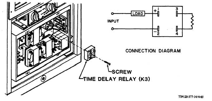
Figure 4-65. Time Delay Relay
a. lnspection
(1) Check for loose wire connections.
(2) Check for cracks, evidence of overheating, and other visible damage. Replace if damaged.
b. Test
(1) Using a multimeter set on lowest OHMS scale, check continuity.
Terminal 1(+) to 2(-)
- Continuity should not be indicated
Terminal 3 to 4
- Continuity should be indicated
(2) Set multimeter at appropriate dc voltage scale.
(3) Apply power across terminals 1 and 2. Voltage indicated should be 24 ± 5 volts dc. After
approximately 30 second time delay, voltages should drop to less than two volts.
(4) Replace time delay relay if it fails any of the above tests.
4-105
|