Order this information in Print

Order this information on CD-ROM

Download in PDF Format


Click here to make tpub.com your Home Page

Page Title: compressor start relay
Back | Up | Next

Click here for a printable version

Google


Web
www.tpub.com

Home


Information Categories
.... Administration
Advancement
Aerographer
Automotive
Aviation
Combat
Construction
Diving
Draftsman
Engineering
Electronics
Food and Cooking
Math
Medical
Music
Nuclear Fundamentals
Photography
Religion
USMC
   
Products
  Educational CD-ROM's
Printed Manuals
Downloadable Books


4-55. TM5-4120-377-14 c.   Removal (1)  Tag  and  unsolder  wire  leads. (2)  Using  screwdriver,  remove  screw  from  time  delay  relay. (3)  Remove  time  delay  relay. d.    Installation (1) (2) (3) (4) (5) (6) (7) Aline  antirotation  pin  and  mounting  holes. Using  screwdriver,  secure  time  delay  relay  to  junction  box  mounting  panel  with  screw. Cut  heat  shrink  tubing  to  approximately  three-quarter  inch  (1.9  cm)  long. Slip  heat  shrinkable  tubing  over  leads. Solder leads in place using tags and wiring diagram. (See fig. 4-20.) Slip  heat  shrinkable  tubing  over  solder  connection  and  shrink  in  place. Remove tags. Follow-on  procedure:  Install  junction  box  cover  and  lower  front  panel.  (See  para  4-47.) Preliminary  procedure:  Remove  junction  box  cover.  (See  para  4-47.) 
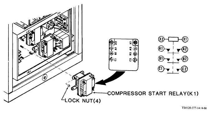
Figure  4-66.  Compressor  Start  Relay 4-106

Privacy Statement - Press Release - Copyright Information. - Contact Us - Support Integrated Publishing

Integrated Publishing, Inc. - A (SDVOSB) Service Disabled Veteran Owned Small Business