|
| |
TM5-4120-377-14
b. Inspection
(1) Check that cover is not bent or punctured. Replace if damaged.
(2) Check that gaskets are not cracked, loose, or missing and that fluid diagram and electrical schematic
plates are in place and legible. Replace gasket and diagram plates as required.
(3) Check junction box housing and panel for cracked welds and loose or missing hardware. Replace or
repair as required.
c. Disassembly/Reassembly. See paragraphs 4-48 through 4-58 for removal/installation of parts.
d. Installation. Using screwdriver, secure junction box cover with four captive panel fastener screws.
Follow-on procedure: Install junction box. (See para 4-46.)
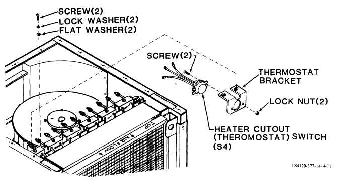
4-60. HEATER CUTOUT (THERMOSTAT) SWITCH (S4)
Preliminary procedure: Remove top panel. (See para 4-28.)
Figure 4-71. Heater Cutout (Thermostat) Switch (S4)
a. Removal
(1)
(2)
(3)
(4)
(5)
Check to see that power has been disconnected.
Tag and disconnect leads.
Using screwdriver and wrench, remove two screws and lock nuts.
Remove heater cutout (thermostat) switch.
If thermostat bracket is to be removed, use screwdriver to remove two screws, lock washers, and flat
washers and remove bracket.
4-112
|