|
| |
5-17.
TM5-4120-377-14
(6) Evacuate and charge the system. (See para 5-10 and 5-11.)
(7) Check that valve stern and hose connection protective caps are in place on valves.
Follow-on procedure: Install rear panel. (See para 4-32.)
Preliminary procedure: Remove junction box. (See para 4-46.)
a. Test
(1) Check to be sure power has been disconnected.
NOTE
The folfowing basic instructions apply to both the equalizing solenoid L2 and the liquid
line solenoid L1.
(2) Disconnect wiring harness connector (P6) from connector (J6) on solenoid valve (L2) or connector
(P5) from connector (J5) on solenoid valve (L1).
(3) Use a multimeter set on lowest OHMS scale to check for continuity between contacts A and B in
solenoid valve connector. If continuity is not found, coil is open and must be replaced.
(4) Use multimeter to check for continuity between each contact in solenoid valve connector and coil
casing. If continuity is found between either contact and case, the coil is grounded and should be replaced.
(5) If continuity checks are satisfactory, apply 24 volts dc from an external power supply across contacts
A and B in solenoid valve connector, and listen for a sharp click when the valve changes position. If a click is
not heard, internal valve problems are indicated and entire valve should be replaced. (Go to para 5-
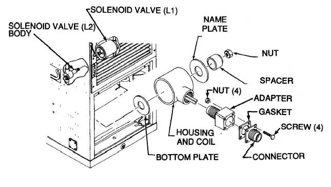
Figure 5-14. Solenoid Valve Coil Replacement (Applied Model 3788)
Change 1
18.)
5-29
|