|
| |
TM5-4120-377-14
b. Installation. If valve body was not removed, go to step (3).
(1) Place the valve body on the tube ends, purge the system with nitrogen and braze the tube joints. (See
para 5-7 and 5-8.)
(2)
(3)
(4)
(5)
(6)
(7)
(8)
(9)
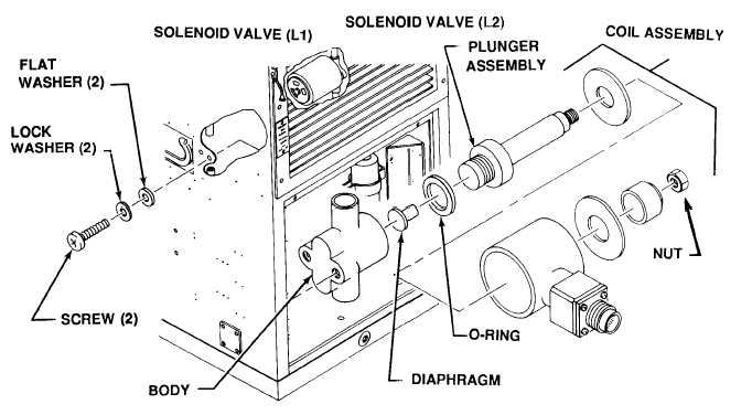
Wing a screwdriver, secure the valve body to the casing side panel with two screws and lock washers.
Check internal surfaces of valve body to be sure it is clean.
Carefully install diaphragm, O-ring, and tube and plunger. Secure to valve body with two screws.
Place coil assembly and data plate onto tube and plunger and secure with nut.
Reconnect connector and harness.
Replace the dehydrator. (See para 5-13.)
Leak test all newly connected joints and those in the repaired area. (See para 5-9.)
Evacuate and charge the refrigerant system. (See para 5-10 and 5-11.)
Follow-on procedure: Install junction box. (See para 4-46.)
5-18.1 SOLENOID VALVES (L1 and L2) (FOR APPLIED MODEL 3788 ONLY)
For testing and replacement of coils, see paragraph 5-17.
Preliminary procedure: Remove junction box. (See para 4-46.)
a. Removal
(1) Check to be sure power has been disconnected.
(2) Discharge the refrigeration system in accordance with paragraph 5-6.
Figure 5-15.1 Solenoid Valves (L1 and L2) (Applied Model 3788)
5-32
Change 1
|