|
| |
TM 5-4120-377-14
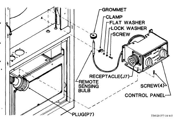
Figure 4-5. Control Panel
Disconnect plug (P7) from receptacle (J7).
Using screwdriver, loosen four captive panel fastener screws in junction box mounting flanges.
Carefully slip junction box out far enough to gain access to control panel mounting screws.
Using screwdriver, remove four screws from control box.
Remove grommet from remote sensing bulb capillary line.
Take care that sensing bulb capillary line is not kinked and that bulb and capillary are not
cut or damaged during removal.
Carefully slip remote sensing bulb down through bulkhead hole and remove control
Using screwdriver, reinstall clamp, flat washer, lock washer, and screw for possible
Reinstall grommet.
Seal hole in grommet air tight with silicone adhesive sealant, item 1, Appendix E.
panel from unit.
future use.
4-12
|