Order this information in Print

Order this information on CD-ROM

Download in PDF Format


Click here to make tpub.com your Home Page

Page Title: Figure 4-6. Sensing Bulb Secured for Remote Mounting
Back | Up | Next

Click here for a printable version

Google


Web
www.tpub.com

Home


Information Categories
.... Administration
Advancement
Aerographer
Automotive
Aviation
Combat
Construction
Diving
Draftsman
Engineering
Electronics
Food and Cooking
Math
Medical
Music
Nuclear Fundamentals
Photography
Religion
USMC
   
Products
  Educational CD-ROM's
Printed Manuals
Downloadable Books


TM  5-4120-377-14 
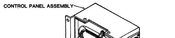
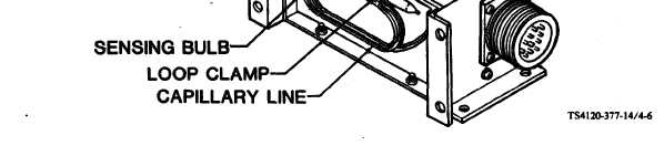
q.  Very  carefully,  coil  capillary  line  and  mount  sensing  bulb  in  loop  clamp  provided  on  back  of  control panel. Figure  4-6.  Sensing  Bulb  Secured  for  Remote  Mounting r.  The  control  panel  is  provided  with  two  sets  of  four  holes.  These  holes  are  sized  for  use  with  0.25  inch (0.64  cm)  diameter  hardware.  The  control  panel  can  be  mounted  using  the  bottom  or  rear  face  holes. s.  Care  should  be  taken  to  locate  the  control  panel  and  sensing  bulb  where  there  will  be  an  accurate temperature    indication. NOTE Do  not  locate  control  panel  on  thin  outside  walls  or  near  heat  producing  equipment  or lights. t.  Secure  the  control  panel  using  appropriate  hardware  in  the  remote  location. u.  Carefully  move  junction  box  into  position  and  secure  with  four  captive  panel  screws. v.  Using  screwdriver,  install  block  off  assembly  using  the  four  mounting  screws  removed  from  the  control panel. 4-13

Privacy Statement - Press Release - Copyright Information. - Contact Us - Support Integrated Publishing

Integrated Publishing, Inc. - A (SDVOSB) Service Disabled Veteran Owned Small Business