 |
|||
|
|
|||
|
Page Title:
MODE SELECTOR SWITCH S1. - Continued |
|
||
| ||||||||||
|
|
 TM5-4120-384-14
4-23. MODE SELECTOR SWITCH S1. - Continued
(8) Remove nut and washer and pull MODE SELECTOR switch from
the
panel.
b.
Test.
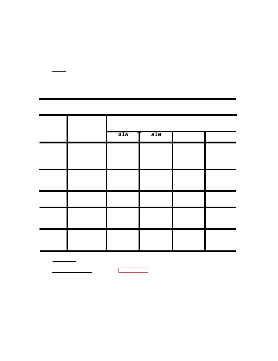
See the mode position chart below and check
continuity at pins indicated to each of the positions indicated.
Replace the switch if continuities are not in accordance with those
indicated.
MODE POSITION CHART
Position
Function
Switch Section and Terminals Connected
S1C
S1D
1
HEAT (HIGH)
12 and 1A 21 and 2C 31 and 3C 41 and 4C
22 and 2B 32 and 3A 42 and 4A
2
HEAT (LOW)
12 and 1A 21 and 2C 31 and 3C
22 and 2B
OFF
3
4
VENT
21 and 2C 31 and 3C
22 and 2B
12 and 1B 21 and 2C 32 and 3B 41 and 4D
COOL
5
11 and 1D 22 and 2B 31 and 3C 42 and 4B
Replace.
c.
Replace
MODE
SELECTOR
switch
if
defective.
Installation.
(See
d.
(1) Slip MODE SELECTOR s w i t c h s h a f t t h r o u g h p a n e l h o l e
and
secure with mounting nut and washer supplied with switch.
(2) Place knob on MODE SELECTOR switch shaft and tighten
setscrews.
4-70
|
|
Privacy Statement - Press Release - Copyright Information. - Contact Us |
