 |
|||
|
|
|||
|
|
|||
| ||||||||||
|
|
 TM 5-4120-386-l4
4-27. UNIT WIRING HARNESS-Continued.
LOCATION/ITEM
ACTION
REMARKS
Removal
a.
Tag all wire leads prior to
Use Wiring
removal.
Diagrams.
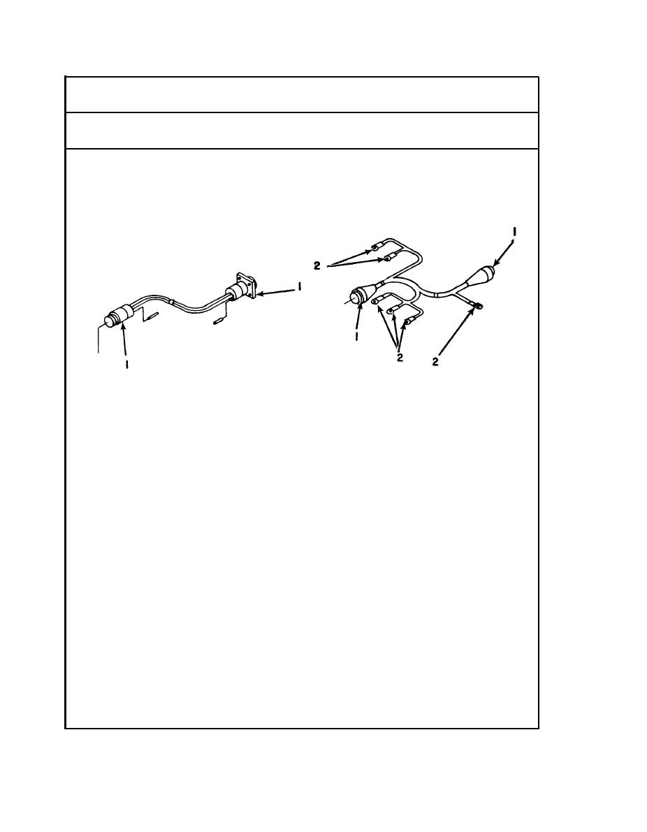
b. Disconnect all connector plugs
(Figures E-1
(1) and terminals (2).
and E-2)
c. Carefully remove harness from
unit.
Test
a.
Test for continuity on wiring
Use Wiring
harnesses.
Diagrams
b. Touch the test probes of a
(Figures E-1 and
continuity tester or multimeter,
E-2).
set on low-resistance range, to
ends of wire and/or corresponding
pin of connector.
c. If continuity is not indicated,
repair or replace wire or damaged
connector.
Repair
Remove the insulation to expose
a.
1/2 inch/1.27 centimeters of bare
wire on each side of break or
damaged insulation.
b. Insert the ends into a splice-
connector; splice and crimp
the connector to make firm
electrical contact.
c. Alternatively, heat-shrink
tubing may be slipped over
one end of the wire before
splicing, then heated after
the splice is made and solder-
ed, so as to cover the spliced
area.
4-66
|
|
Privacy Statement - Press Release - Copyright Information. - Contact Us |
