|
| |
TM5-4120-387-14
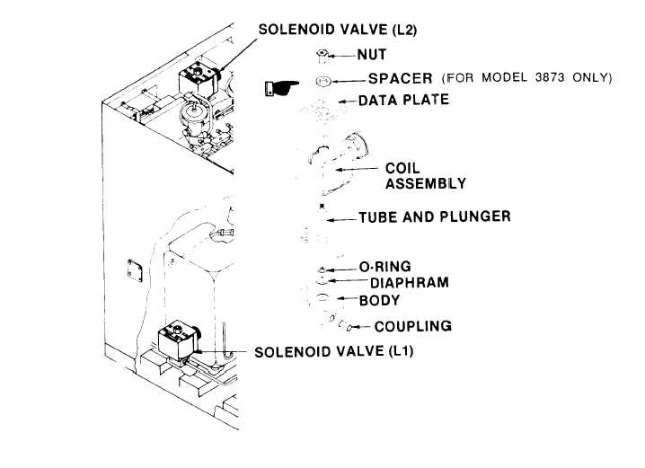
Figure 5-16. Solenoid Valves (L1 and L2)
(2) Remove nut that attaches coil to valve body. For Model 3873, also
remove spacer,
(3) Remove coil assembly and data plate.
(4) Remove two screws that attach tube and plunger assembly to valve
body.
Remove tube and plunger assembly, and all other removable internal
components from valve body.
(5) Check valve body for visible damage.
Normally valve body
replacement is unnecessary,
If valve body is in good condition, skip steps (7) thru
(9).
(6) Using screwdriver, remove two screws and Iockwashers that attach
base of valve body to unit.
5 - 4 2
Change 3
|