|
| |
TM 55-8145-221-14&P
0031 00-3/4 blank
LIGHT ASSEMBLY (EXTERIOR) – Continued
0031 00
ASSEMBLY.
1.
Install bushing (14, Figure 1) in box (11).
2.
Apply sealant (Item 3, WP 0078 00) to threads of adapter (16).
3.
Screw box (11) onto adapter (16).
4.
Install box (11) on container wall (17) with two screws (15).
INSTALLATION.
1.
Push wiring (12) through bushing (14) and into box (11).
2.
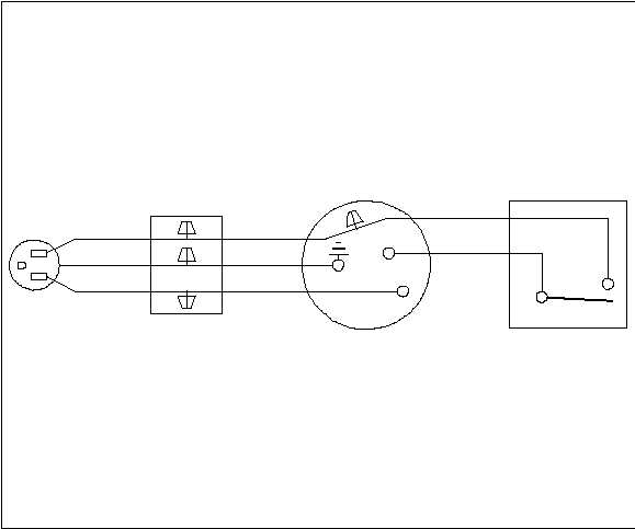
Remove tags and connect wiring (12) as shown, and install three wire nuts (13) (reference Wiring Schematic, Figure 2).
3.
Tighten bushing (14, Figure 1).
4.
Install gasket (10, Figure 1), cover (9), and two screws (8) on box (11).
5.
Install clamp (6) on power cable (1) and secure clamp to bracket (7) with screw (5), lock washer (4) (Item 27, WP 0078
00) and nut (3).
Black
Black
Black
White
Green
Black
Green
White
Junction Box
Figure 2. Wiring Schematic
Switch
Brass
Silver
Light
Fixture
END OF WORK PACKAGE.
|